Triple-check that you've got all your parts. You should have everything listed in this photo before getting started:
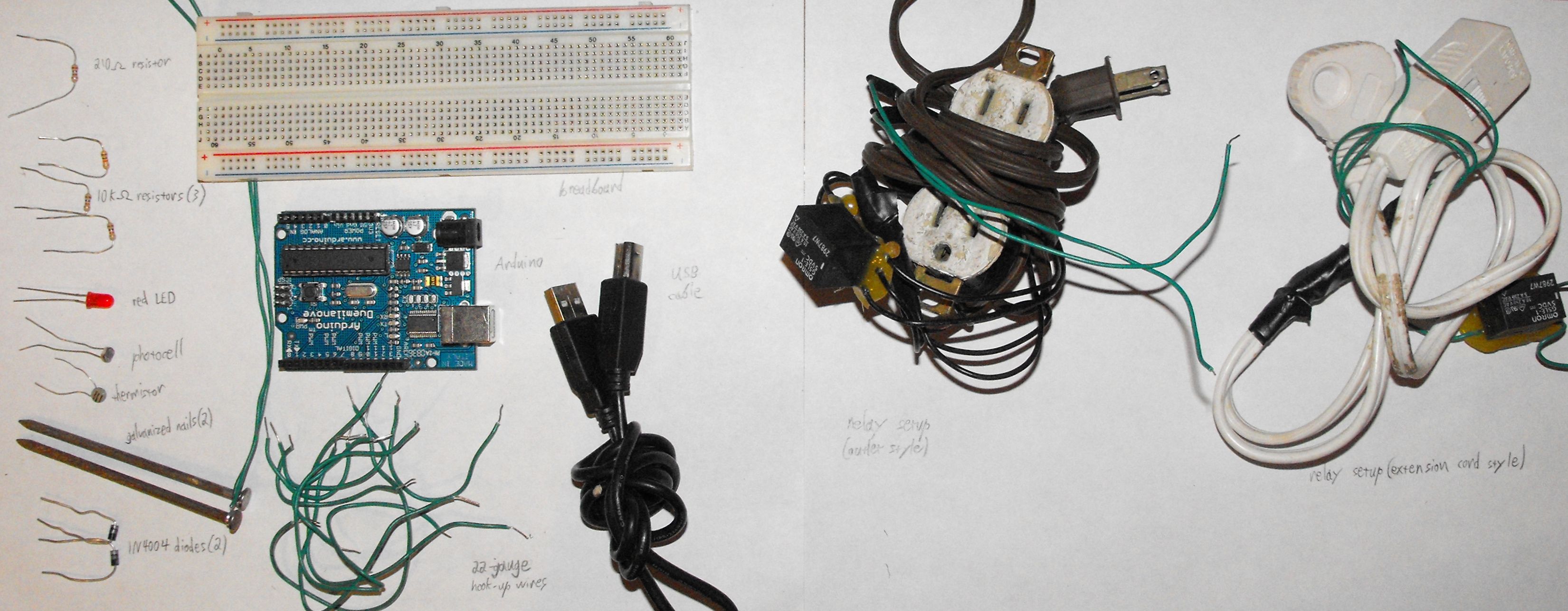
Now that you've got all your parts, it's time to connect them together and create your Garduino. If you're an ardent arduinaut, the schematics are probably all you need to get going. For the rest of us, here's a step-by-step guide to hooking up your sensors and relays. Click on each picture to see a much-bigger version.
Triple-check that you've got all your parts. You should have everything listed in this photo before getting started:
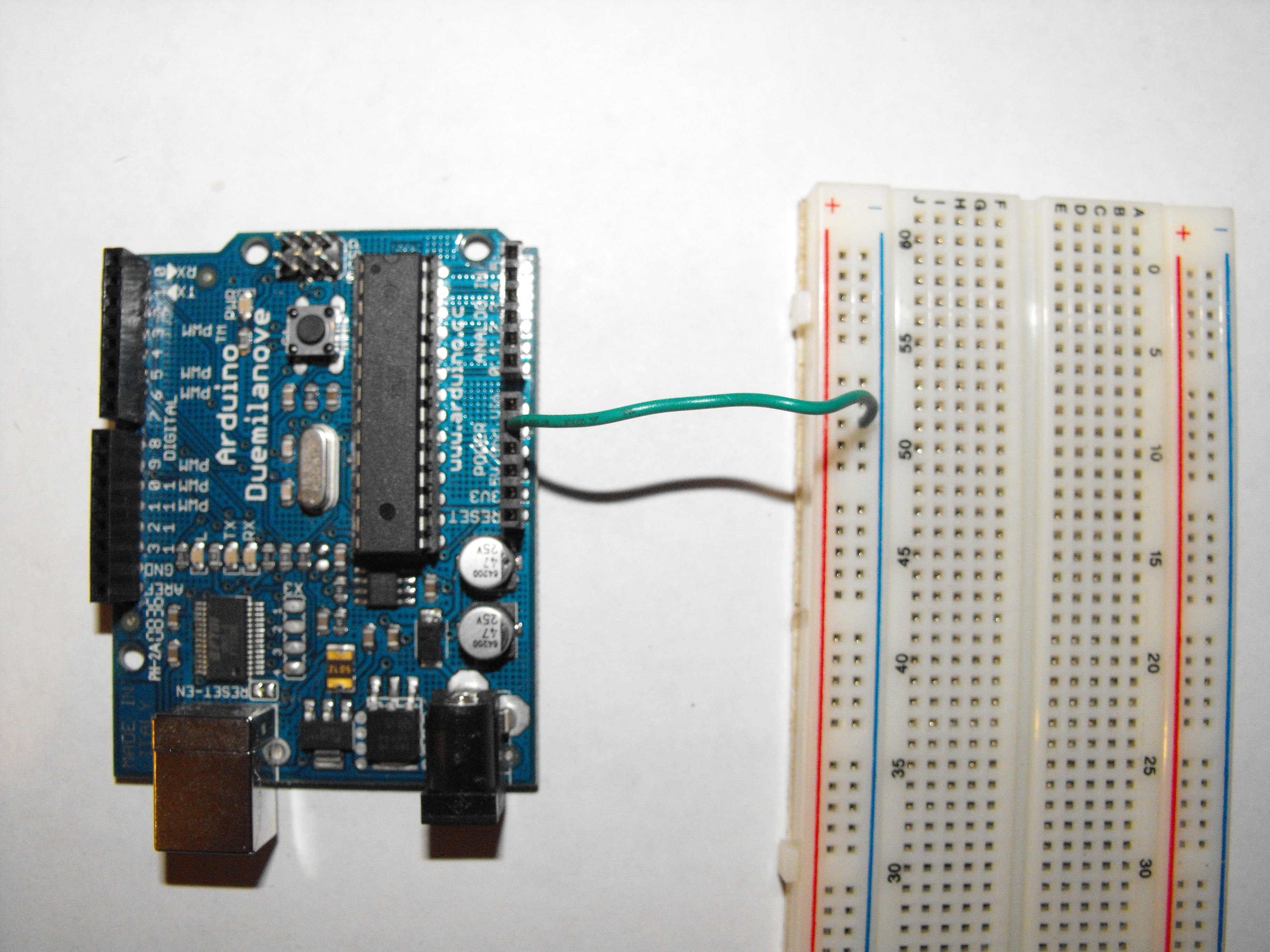
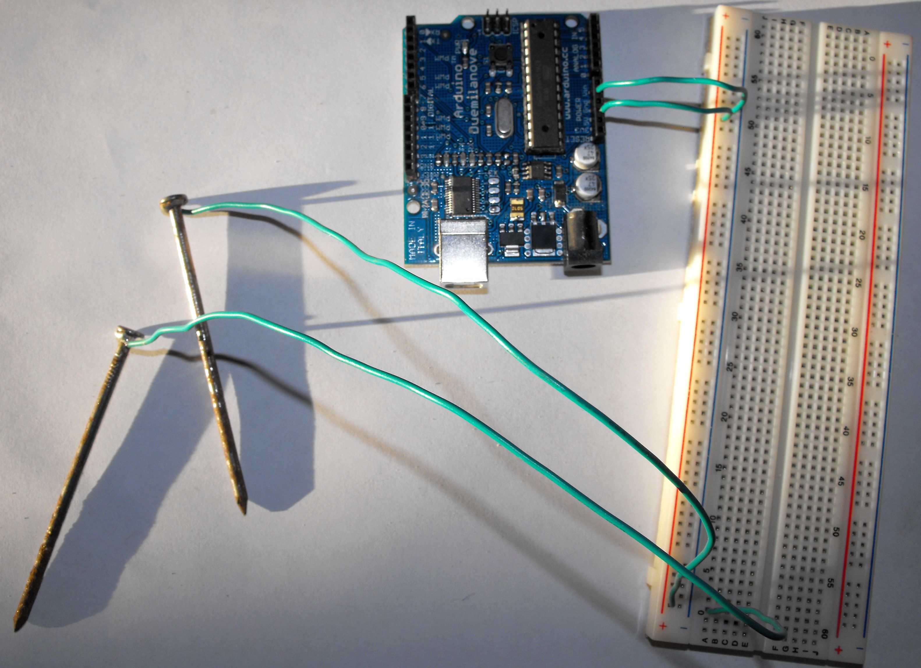
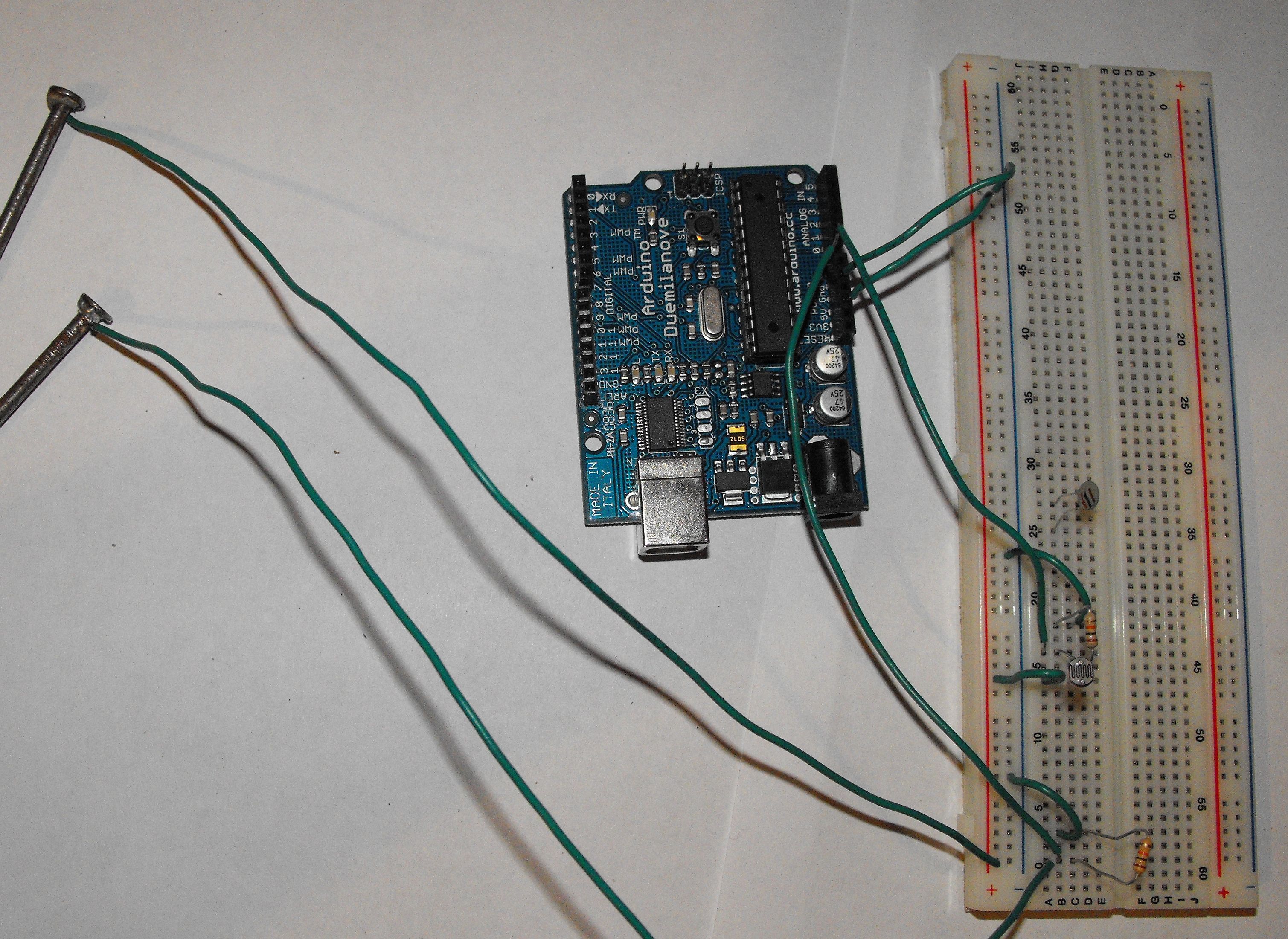
Connect a wire between ground on your Arduino and the ground column on your breadboard. You'll use this column on the breadboard as ground for the rest of the circuit:
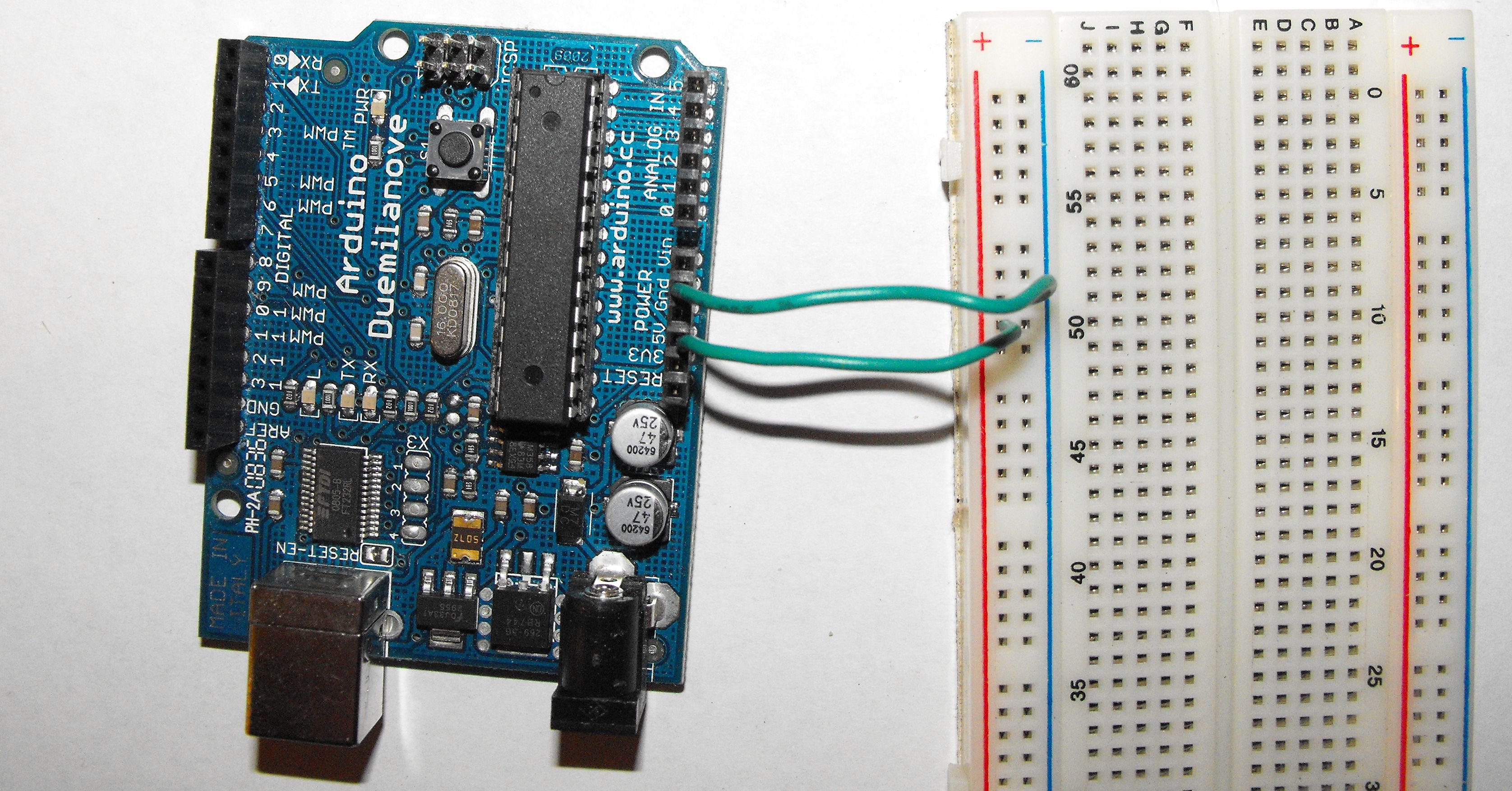
Connect a wire between +5V on your Arduino and the positive column on your breadboard. You'll use this column on the breadboard as ground for the rest of the circuit:
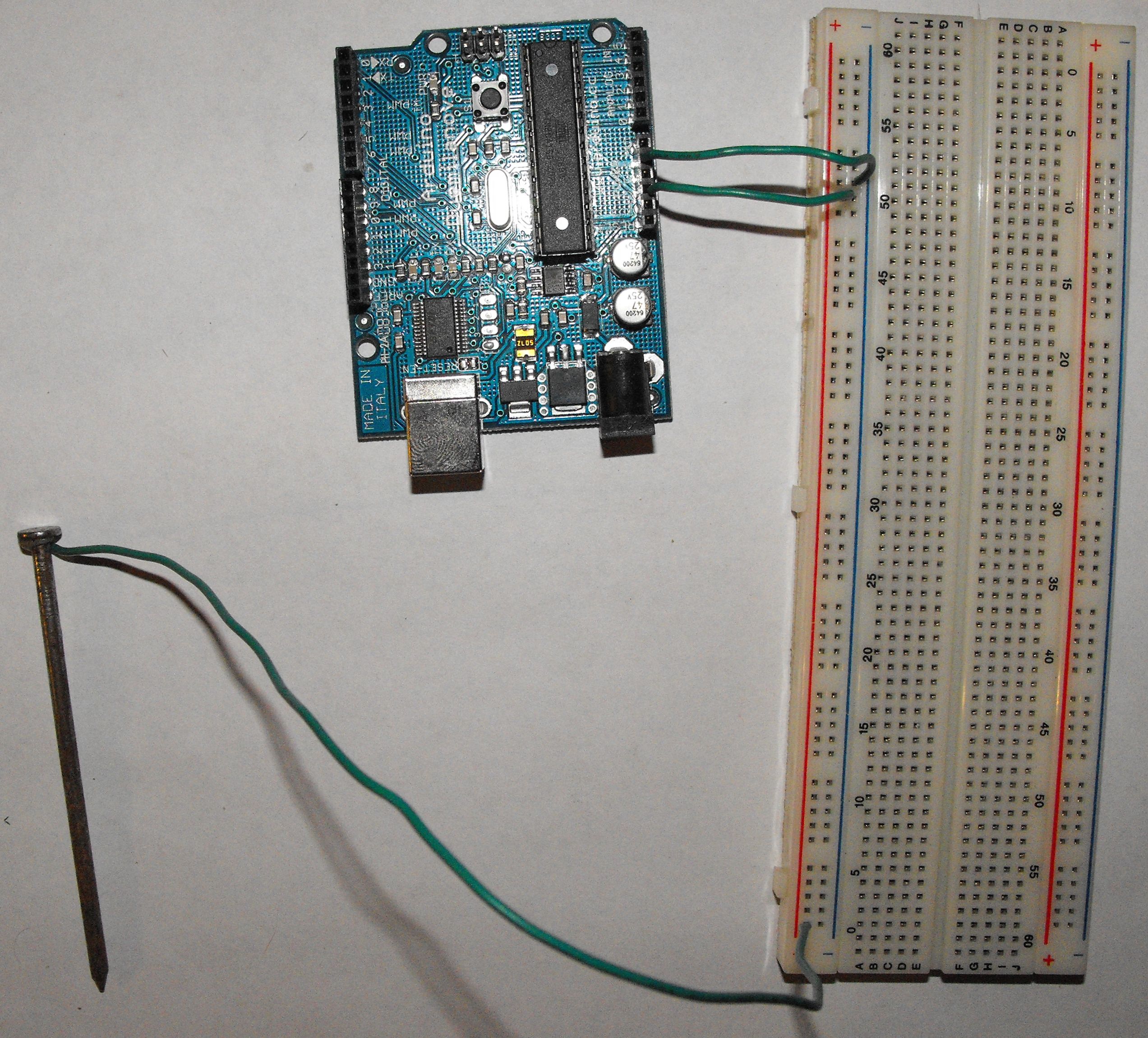
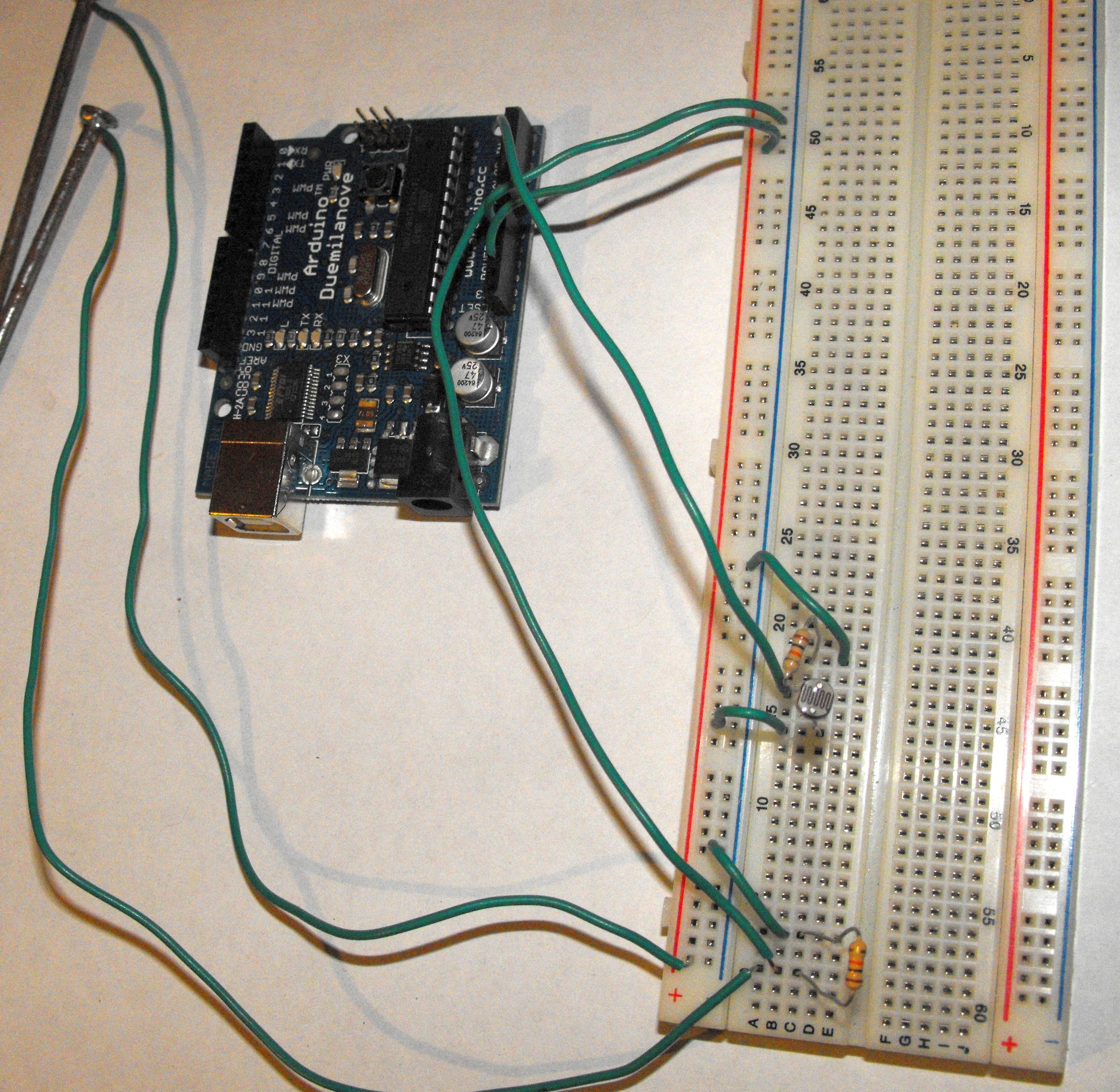
Connect one of the moisture sensors to +5V on the breadboard:
Connect the other moisture sensor to a new row on the breadboard:
Connect one of the 10k-ohm resistors to the same row as the moisture sensor and a new row:

Connect a wire from analog 0 on your Arduino to the same row as the resistor and moisture sensor:
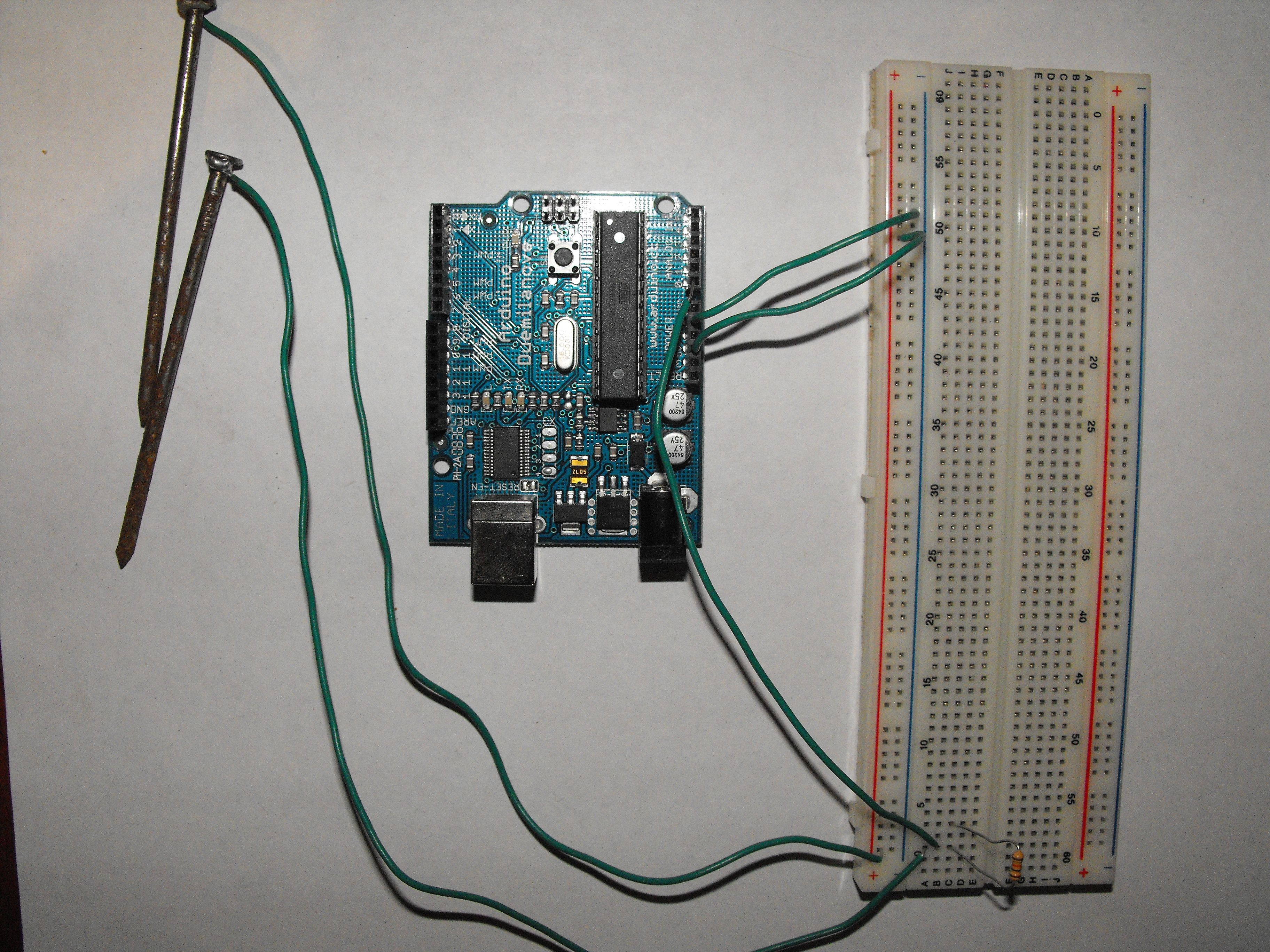
Connect the other end of the resistor to ground:

That's it for the moisture sensor. Now we'll connect the light sensor.
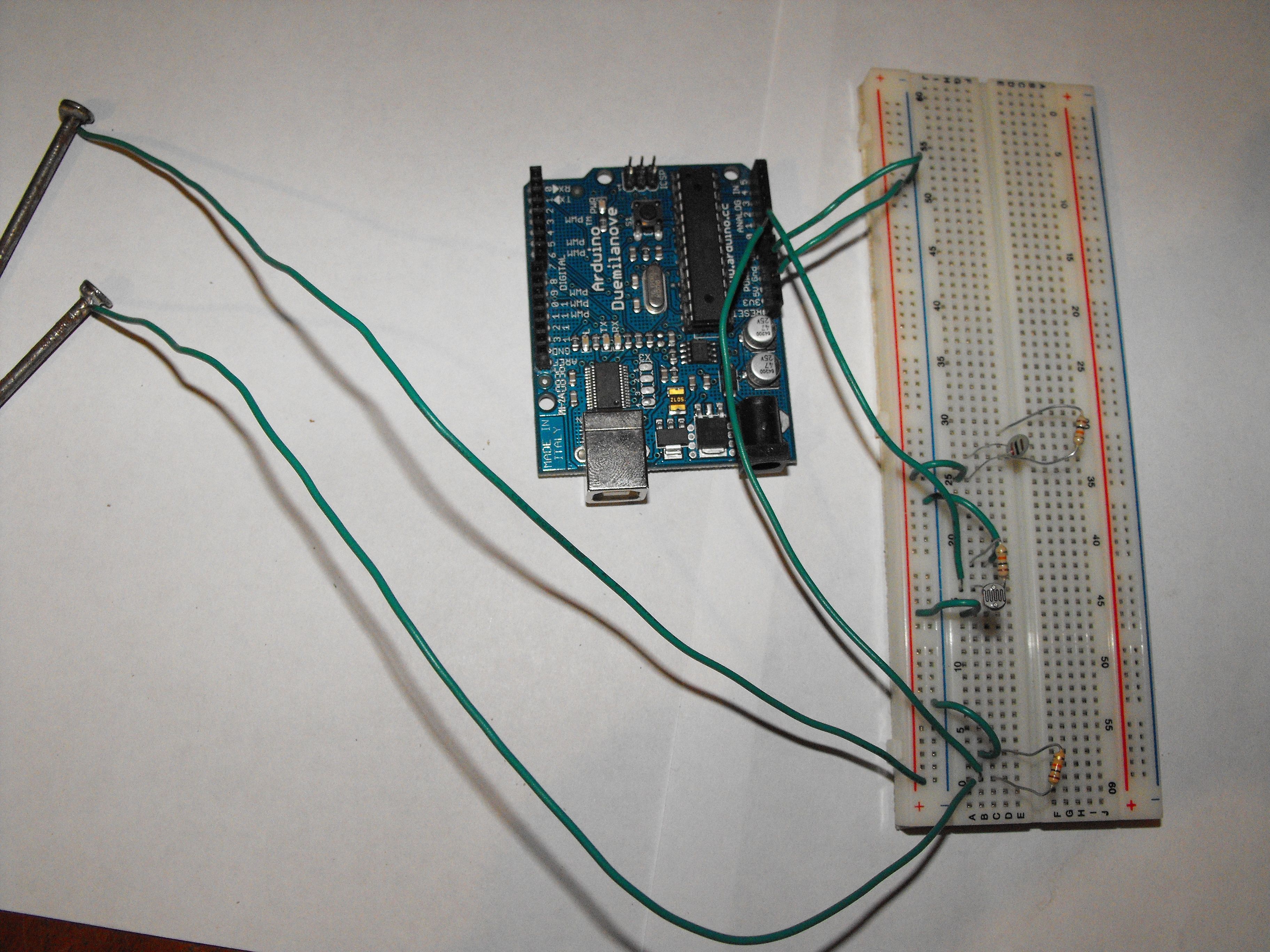
First, connect the photocell to 2 new rows on the breadboard:
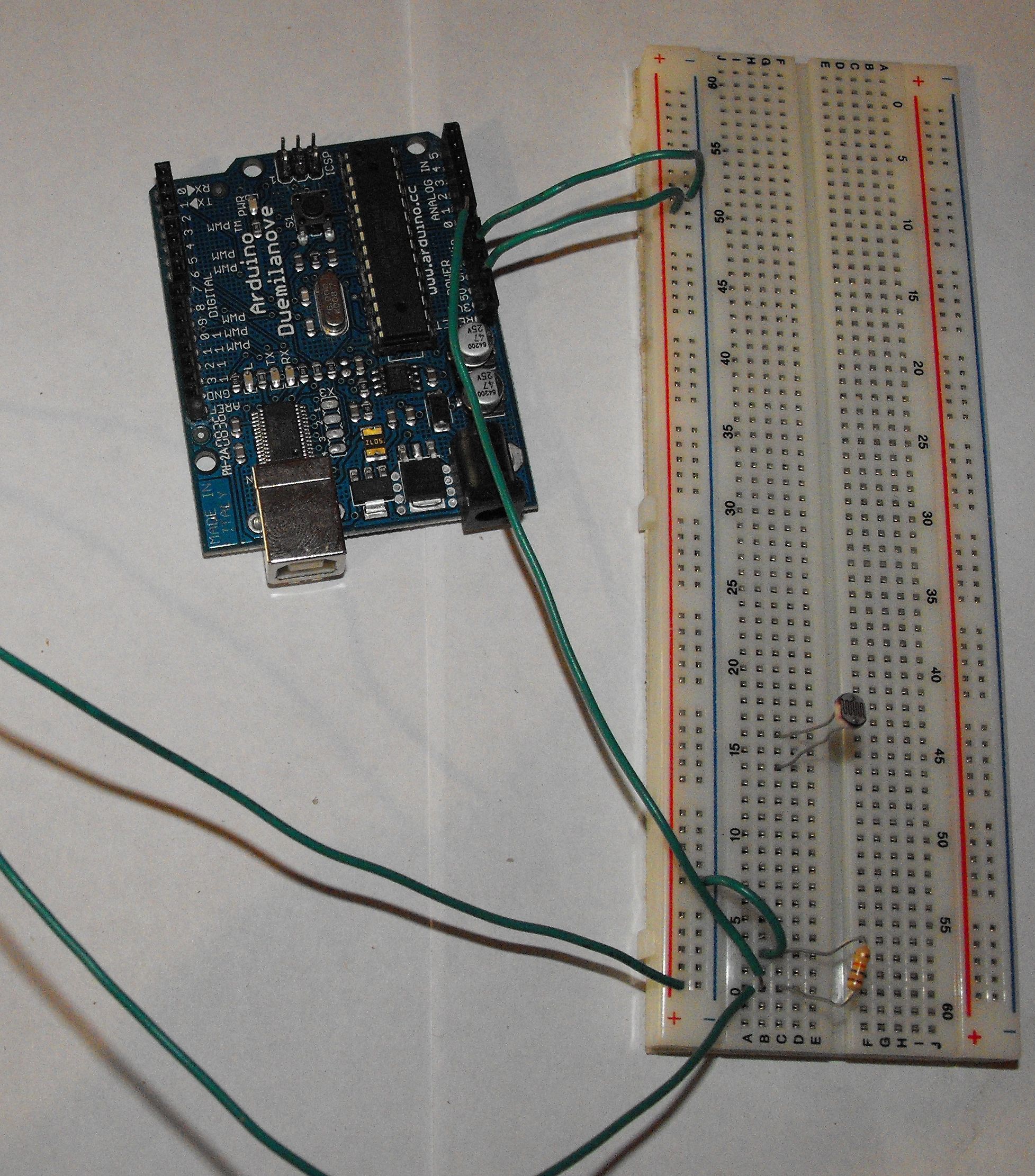
Connect a wire between one row the photocell touches and the positive column:

Connect one of the 10k-ohm resistors to the other row the photocell touches and a new row:
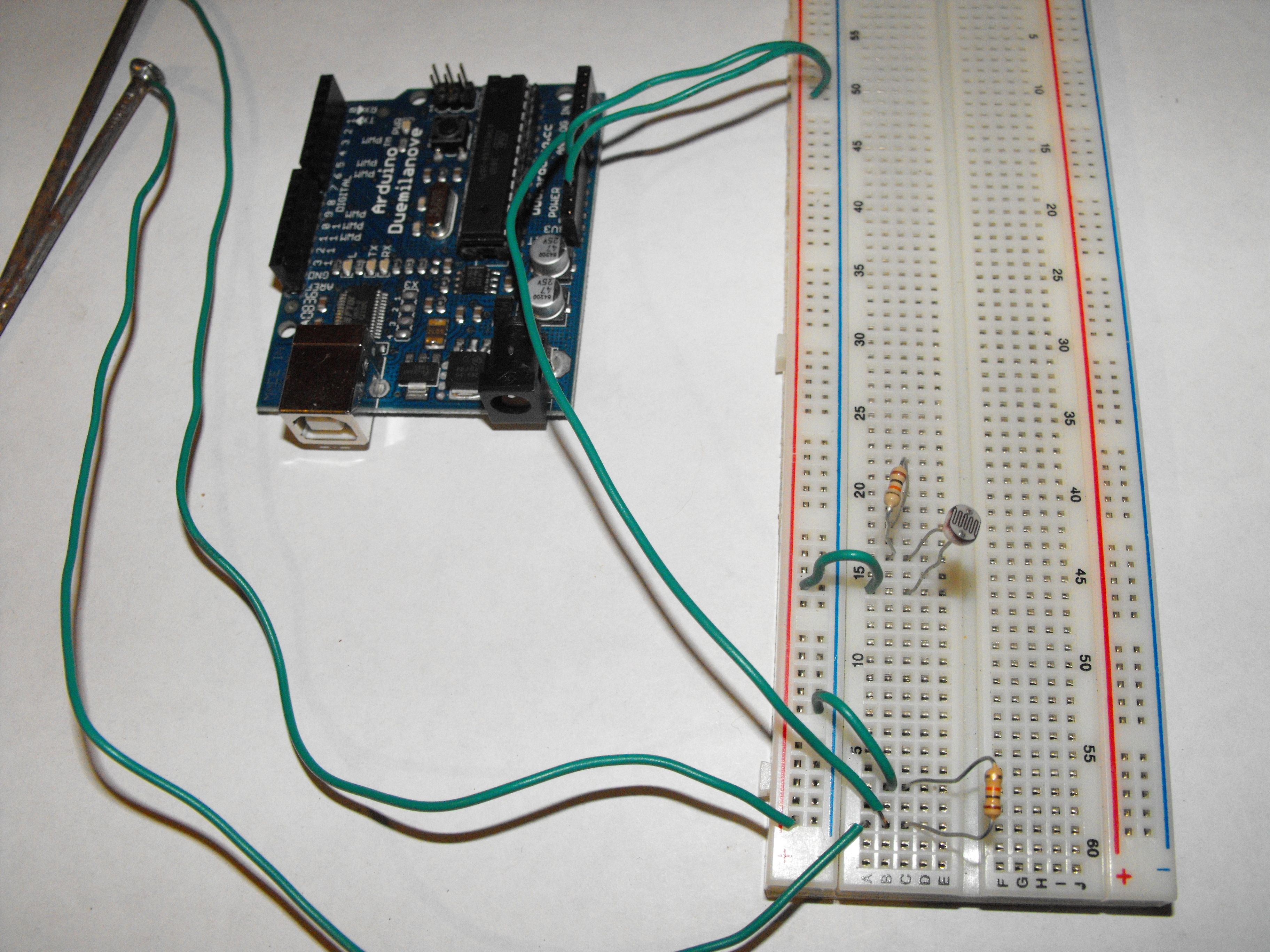
Connect a wire between the photocell-resistor row and analog 1 on your Arduino:

Connect the other end of the resistor to ground:
Congratulations: you've given your Arduino the ability to sense soil moisture and light intensity. Now, we'll add a sense of temperature.
First, connect the thermistor to 2 new rows on the breadboard:
Connect a wire between one row the thermistor touches and the positive column:

Connect the last of the 10k-ohm resistors to the other row the photocell touches and a new row:
Connect a wire between the thermistor-resistor row and analog 2 on your Arduino:

Connect the other end of the resistor to ground:
All 3 of our sensors are now connected: if we've got everything set up correctly, we can now sense soil moisture, light intensity, and temperature. Next, we'll connect an LED to indicate if we drop below a healthy temperature for our plants.
Note which lead is longer on the LED; this is the positive lead:
Connect the LED to 2 new rows on the breadboard. In these pictures, we connected the positive lead to row 5 on the breadboard:
Connect the 210-ohm resistor to the positive lead of the LED and a new row:

Connect the negative lead of the LED to the ground column:

Connect the other lead of the 210-ohm resistor to digital 2 on your Arduino:
Next, the heavy lifters: our relay setups. These will let us turn lights and pumps on and off in response to hours of sunlight received and soil moisture.
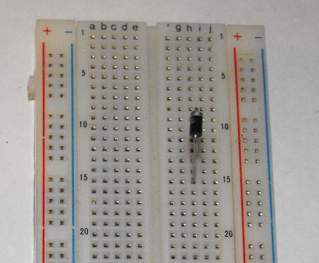
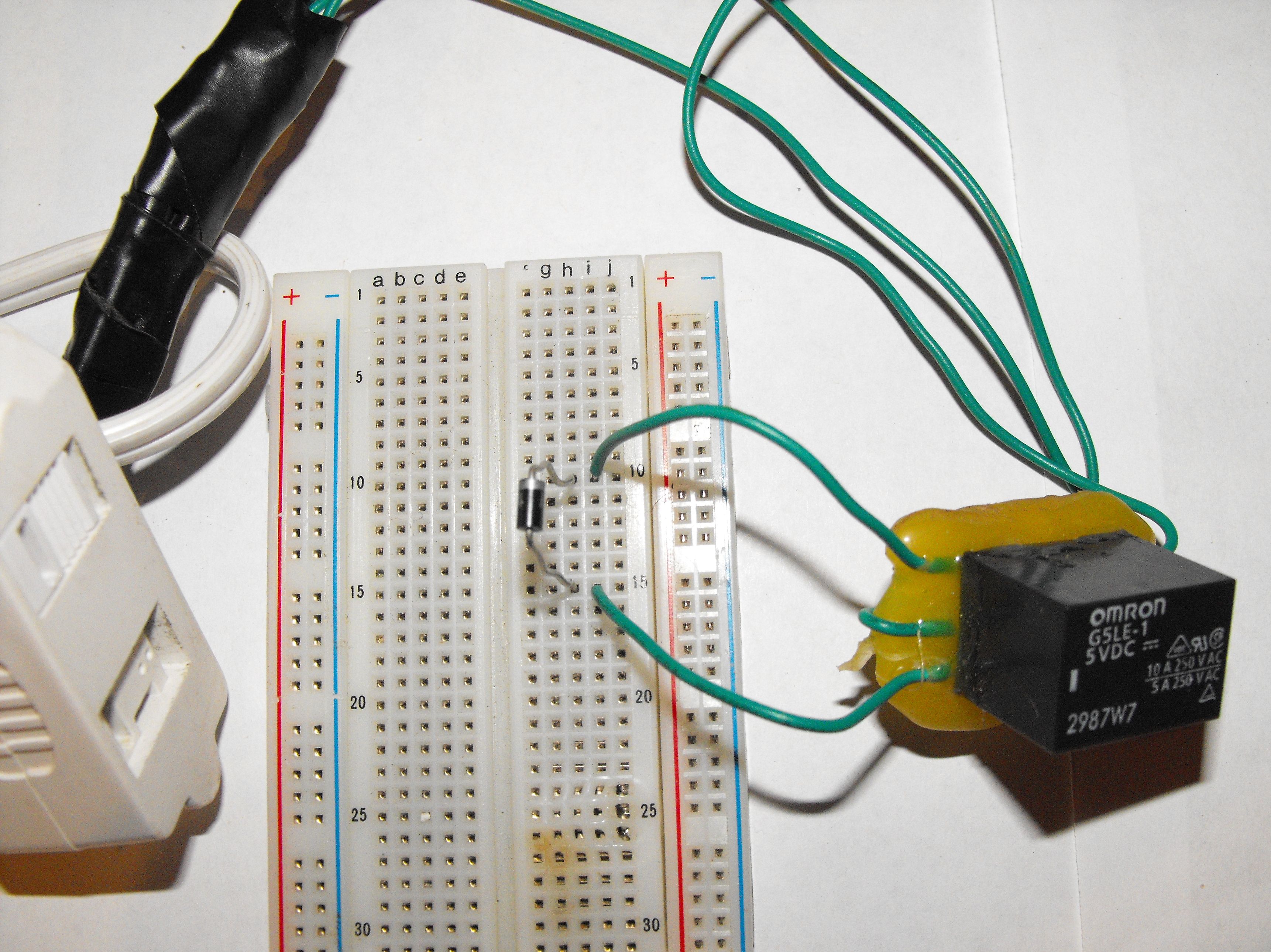
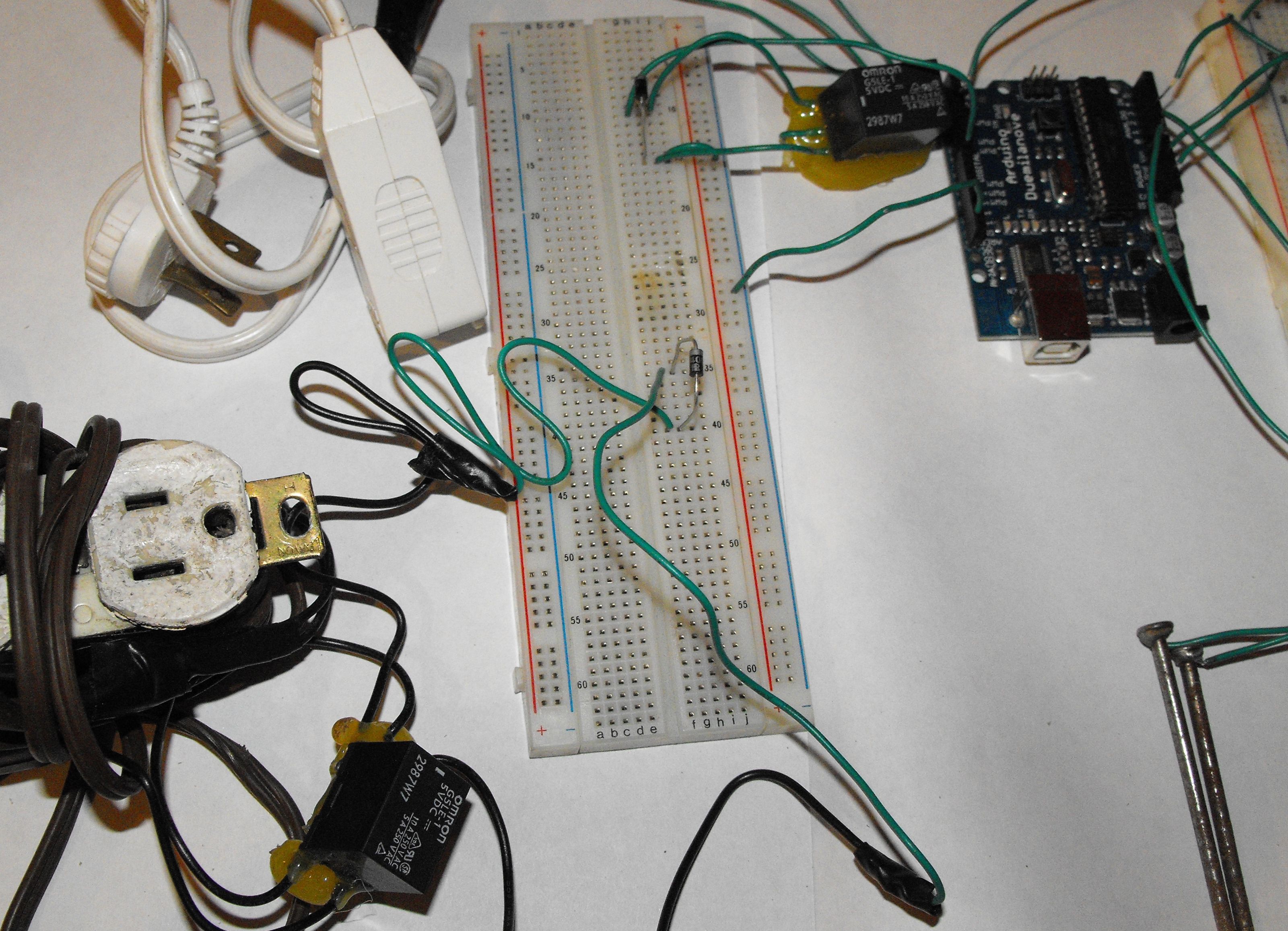
Connect one of your diodes to 2 unused rows on the breadboard (I've used a separate breadboard for the relays to make things easier to see but, of course, you don't need to.):
Connect the bottom left lead of your relay (if you're looking at it from the top, with the leads down) to the end of your diode that does NOT have a line on it:

Connect the upper left lead of your relay to the other end of the diode:
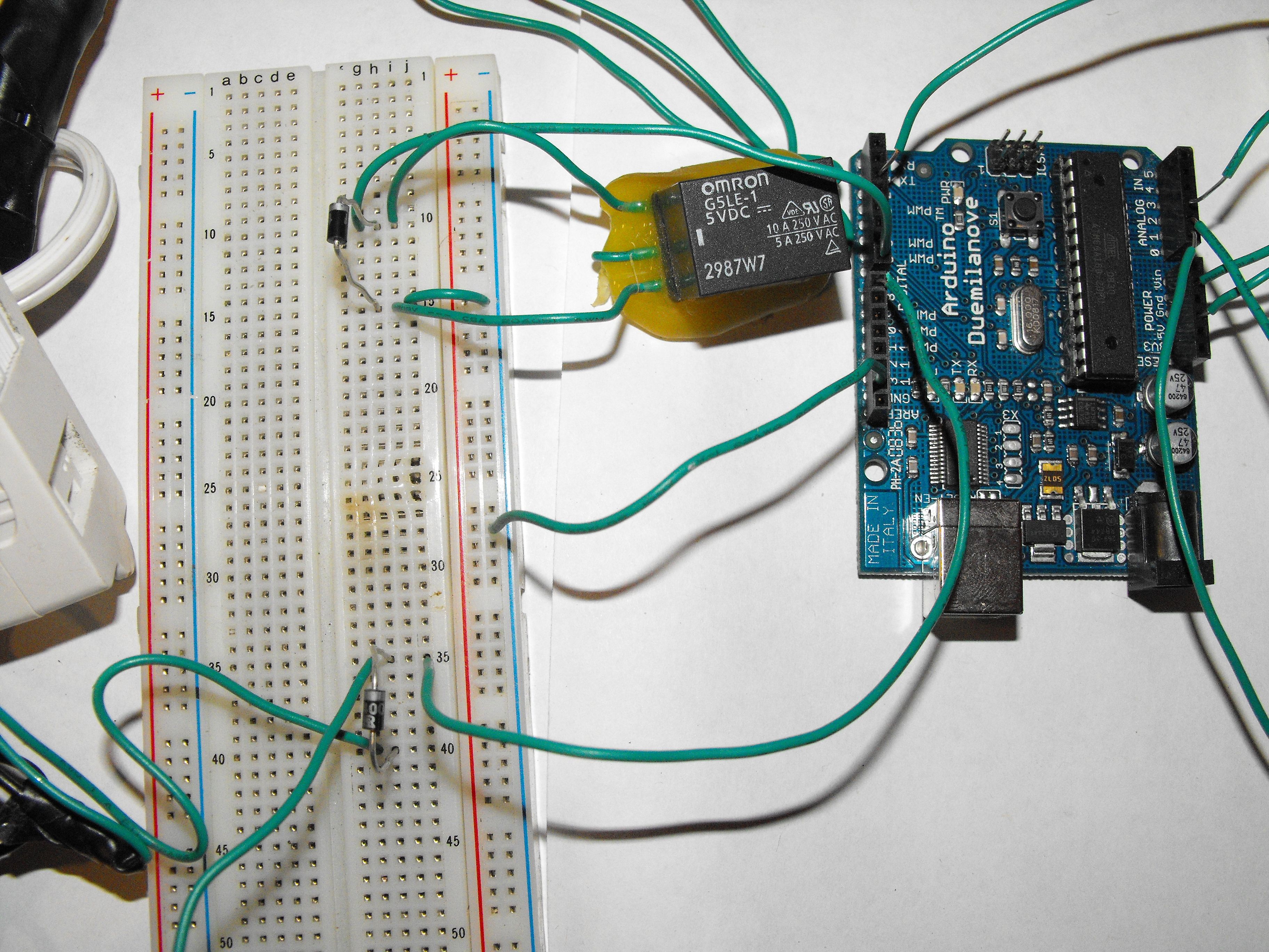
Connect a wire between ground on your Arduino and the ground column on your breadboard (if you're using the same breadboard for relays as you did for sensors, you can continue to use the ground column you've already created):
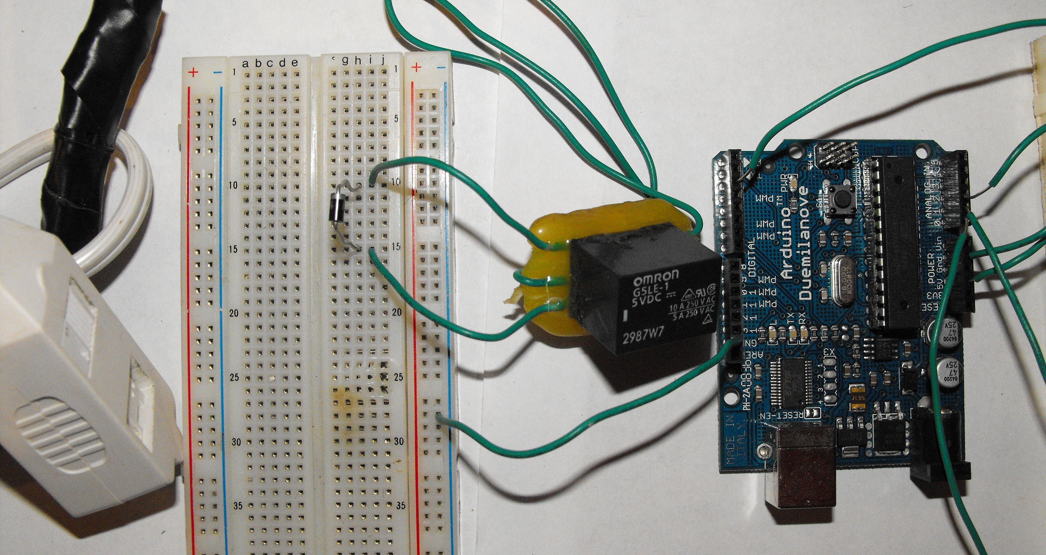
Connect the row containing the negative lead of your diode (the one with the band) and the upper left lead of your relay to digital 7 on your Arduino:

Connect the positive lead of the diode to your ground column:
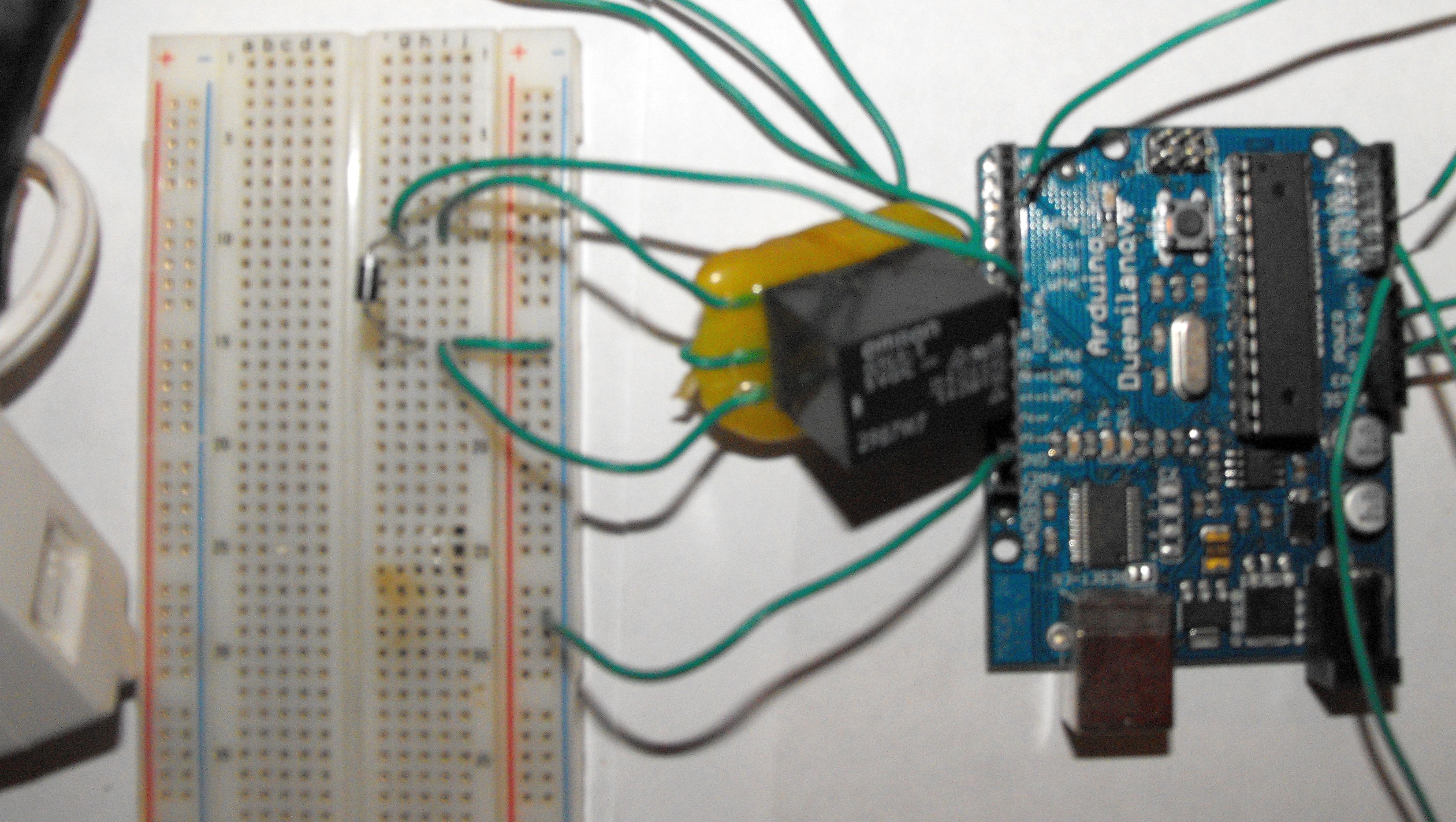
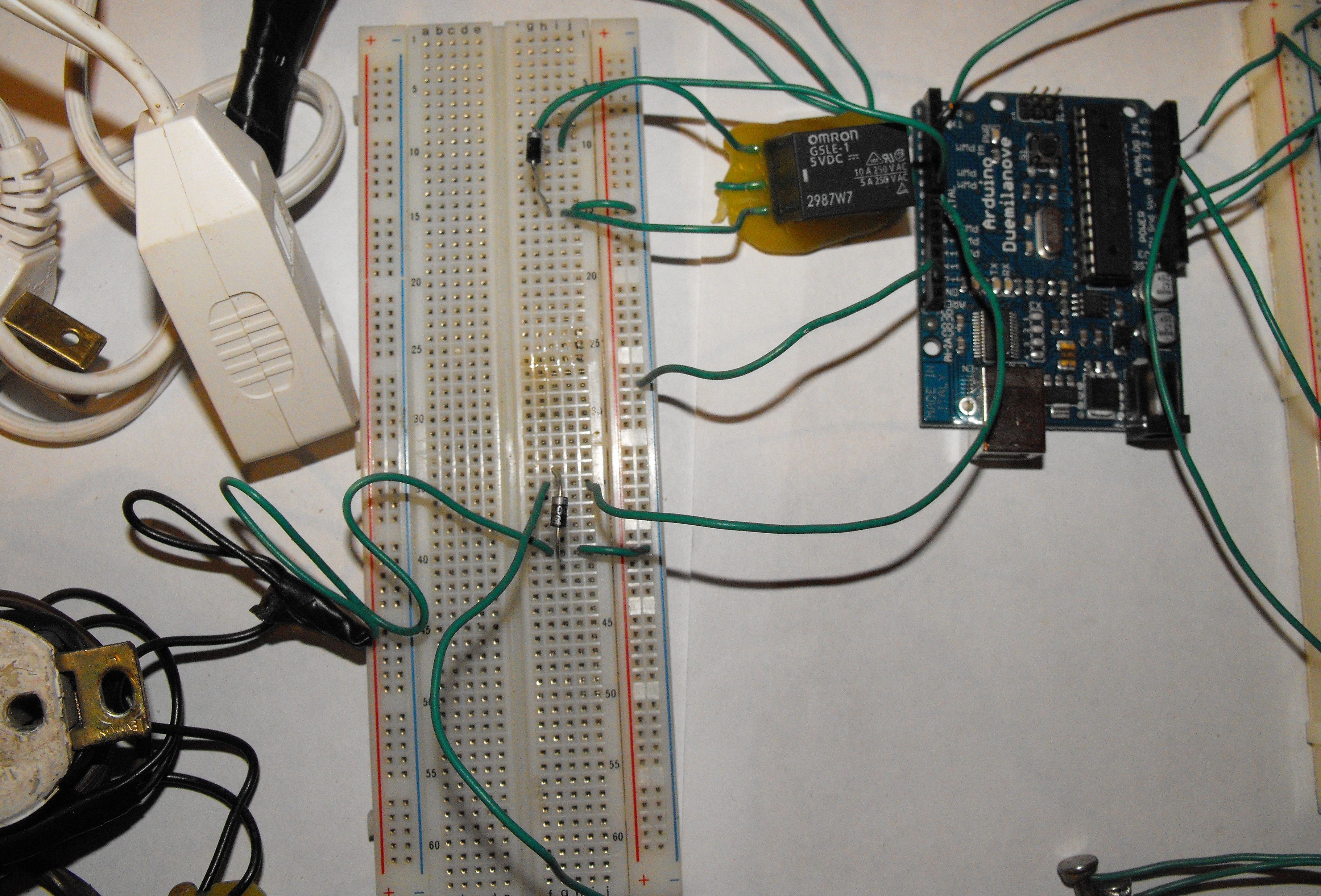
That's it for connecting the first relay; we'll do the same for the second relay. Connect the bottom left lead of your second relay to the positive lead of your second diode:
Connect the upper left lead of your second relay to the other end of the second diode:
Connect the row containing the negative lead of your second diode (the one with the band) and the upper left lead of your second relay to digital 8 on your Arduino:
Connect the positive lead of the second diode to your ground column:
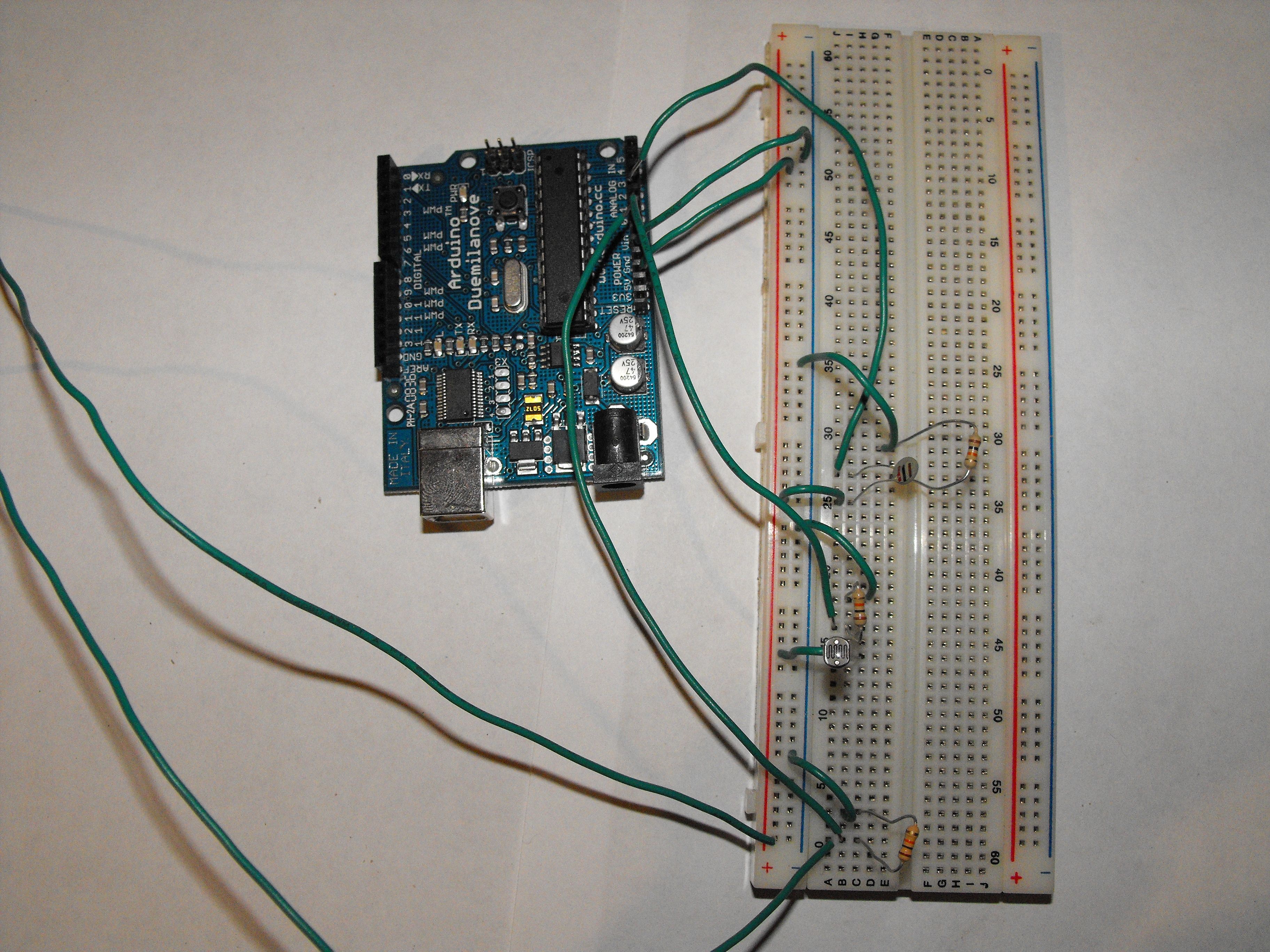
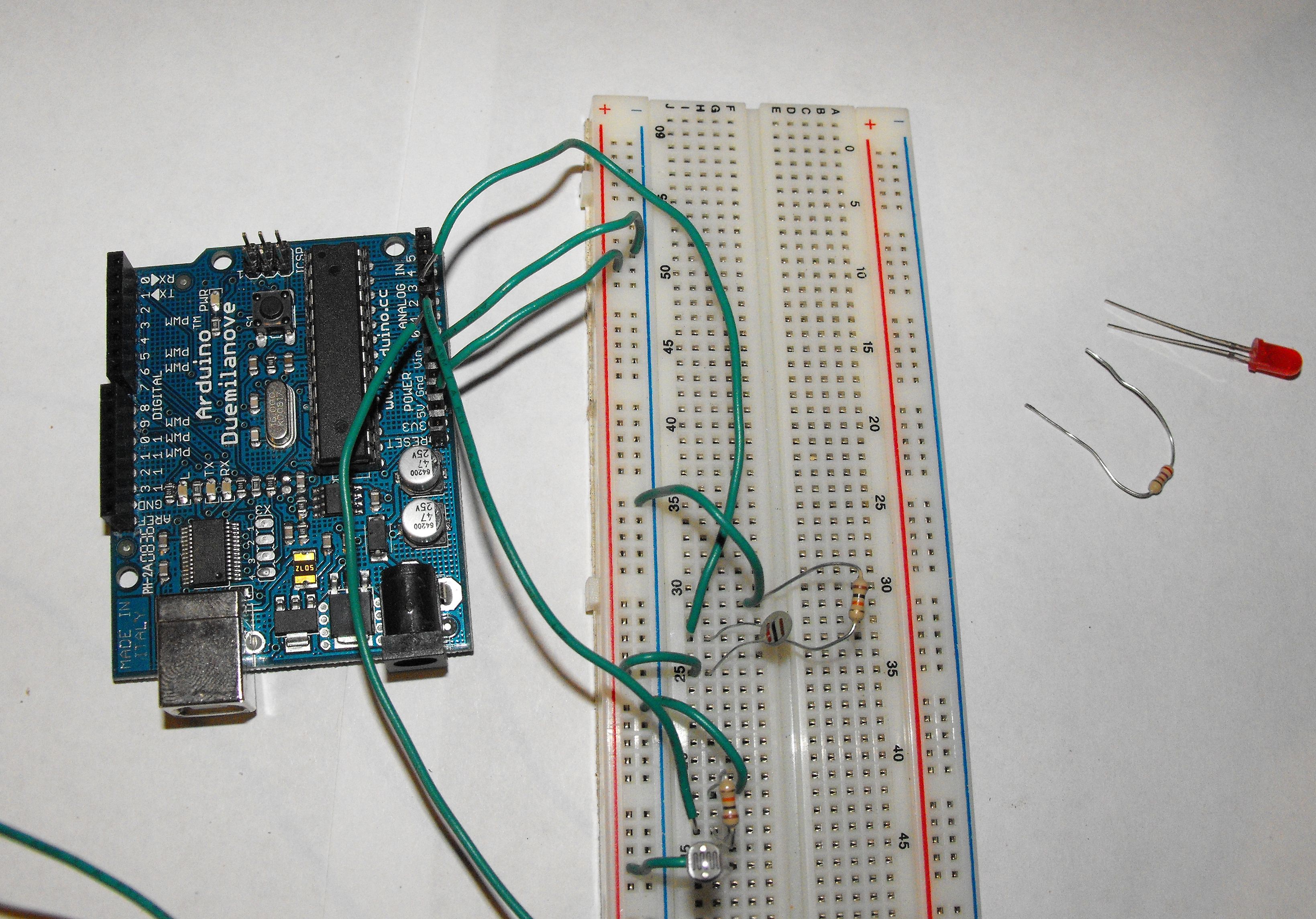
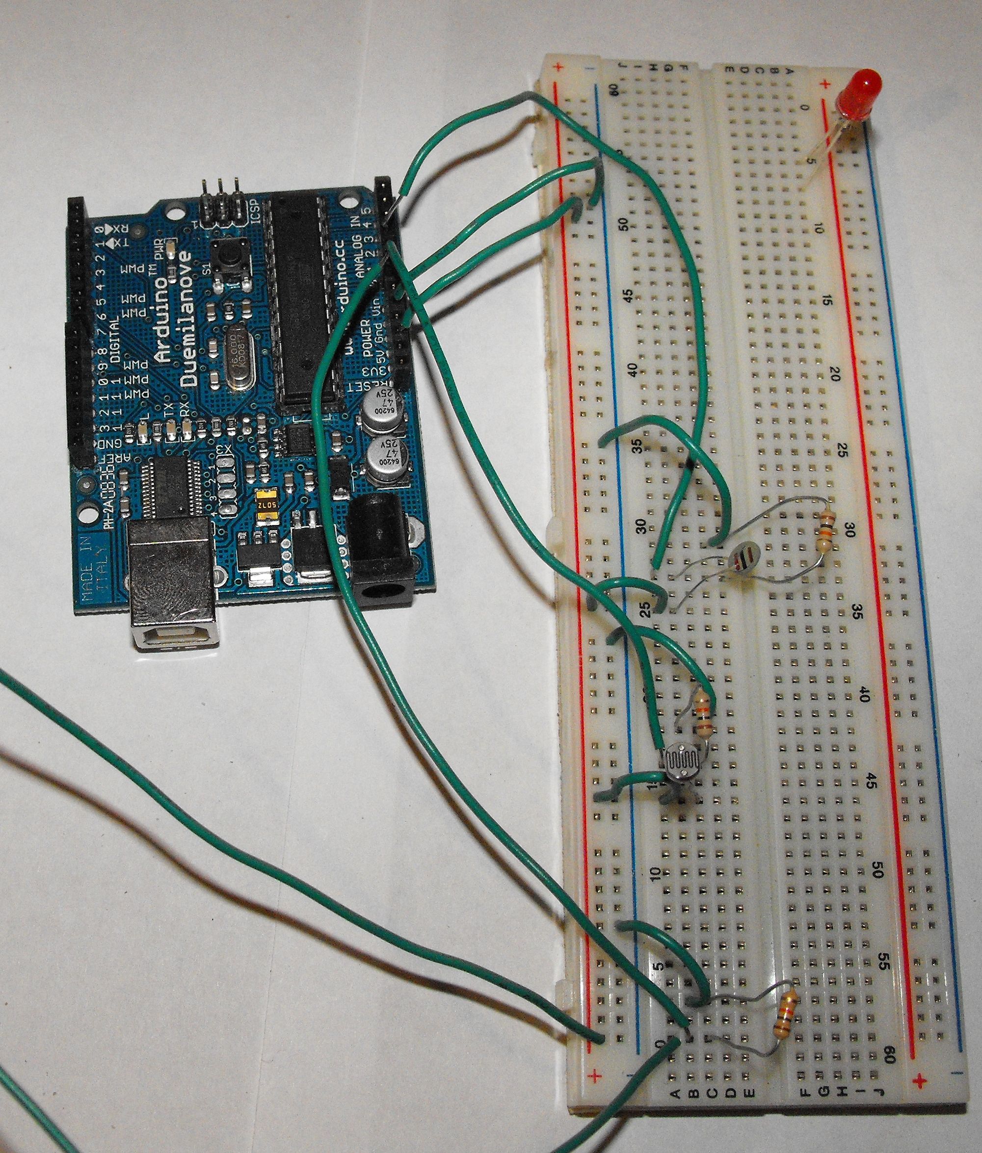
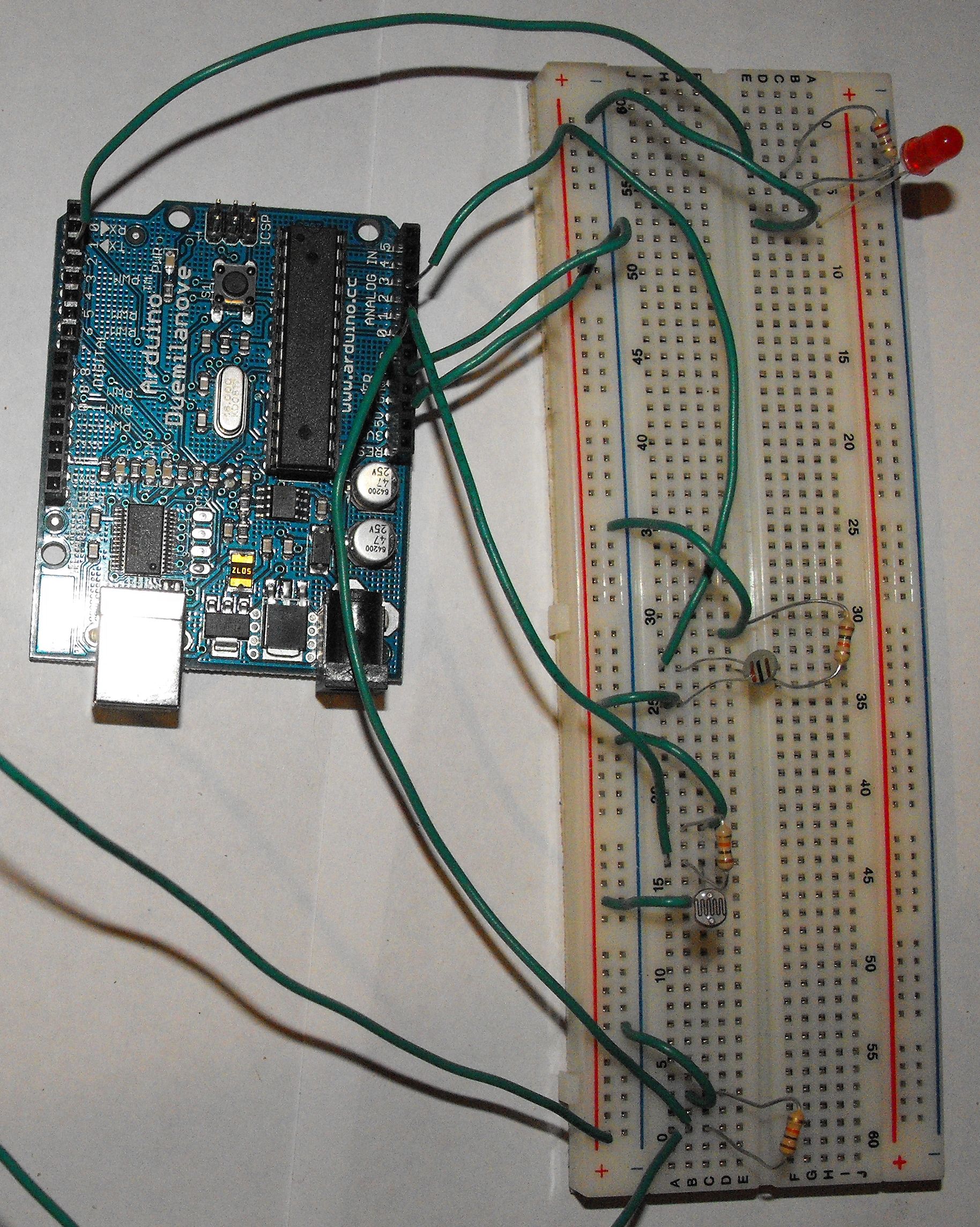
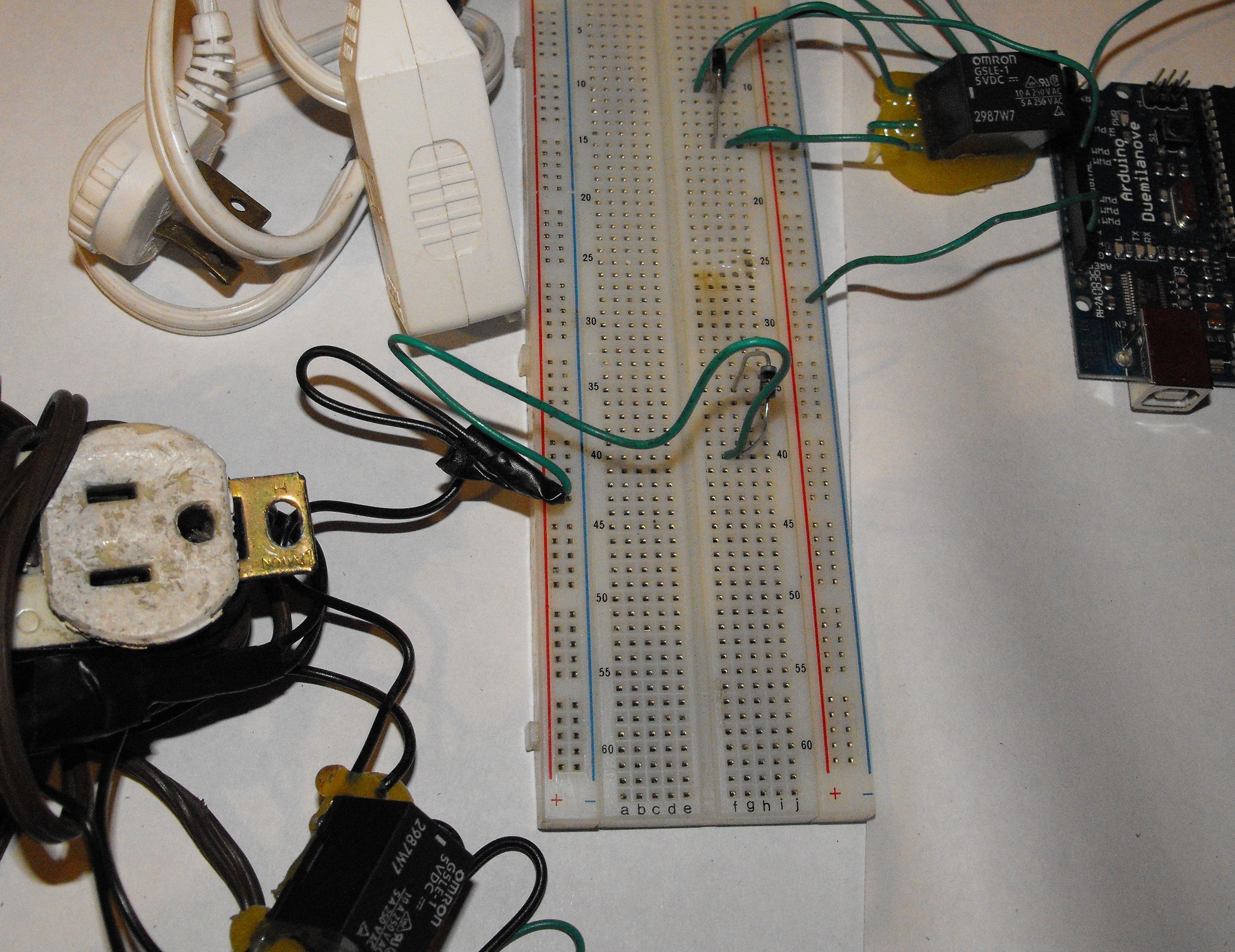
Check your completed circuit:
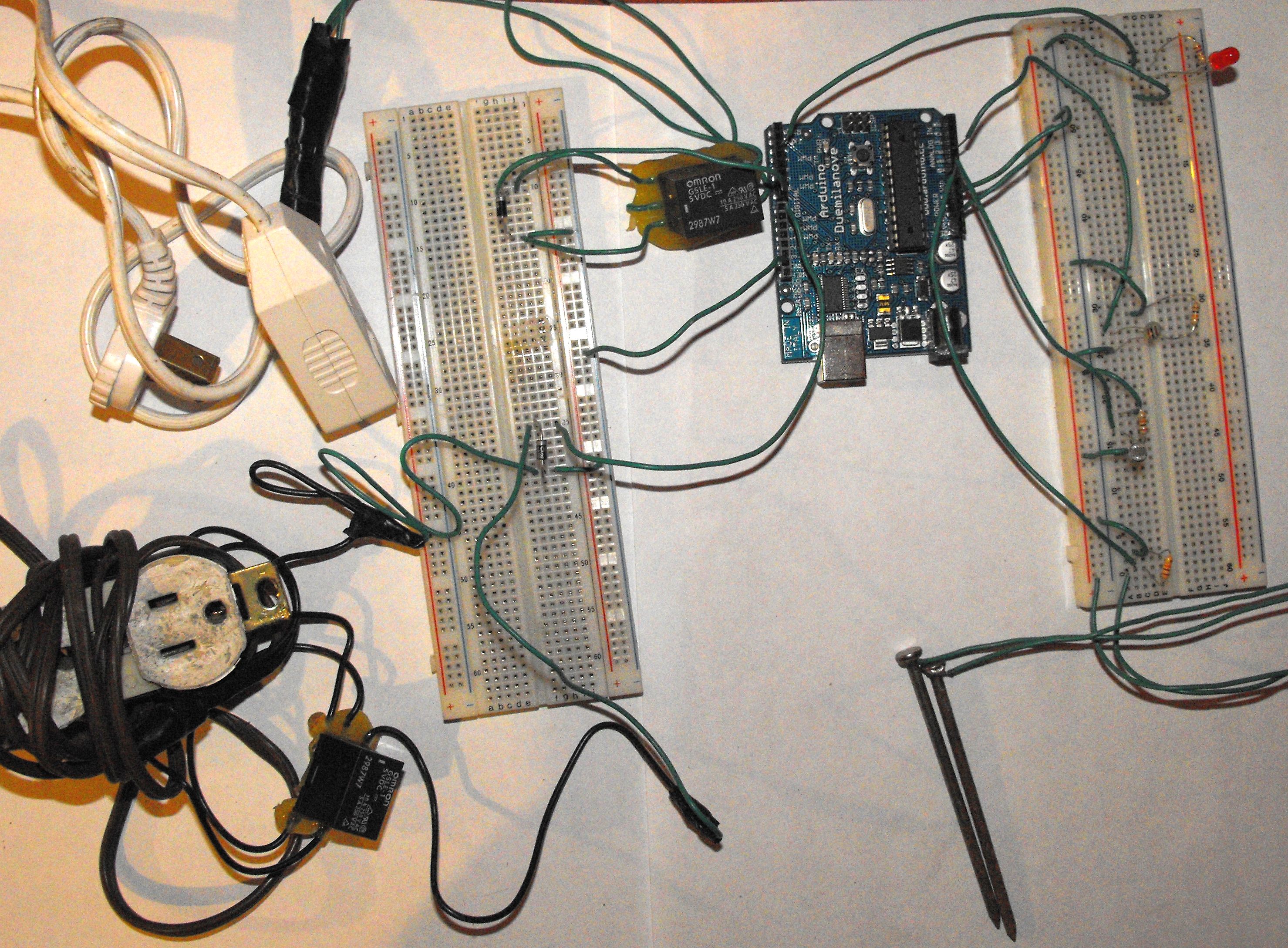
If your circuit seems something like this, congratulate yourself! You're now ready to test and calibrate your sensors.