Thanks for purchasing (or otherwise choosing to build) the Garduino Shield. These step-by-step instructions will help you get your Garduino up and running.
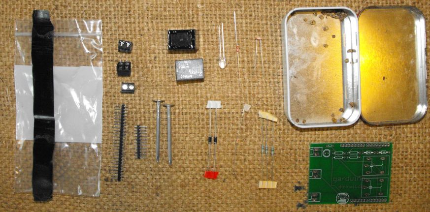
Checking your Kit
Here's what your basic kit will include:
The deluxe kit is the same as the basic but also includes:
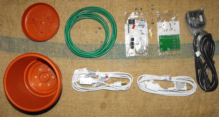
A 6" planter as the main shipping package (instead of the Altoids-style tin; less waste!)
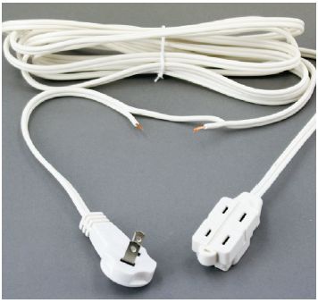
2 extension cords (to be controlled by the relays)
~8' of 1/4" plastic irrigation tubing
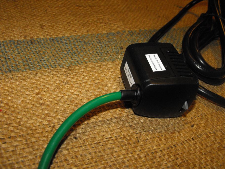
A submersible mini pump, rated at 66 gallons per hour
If anything is missing, contact us and we'll fix that.
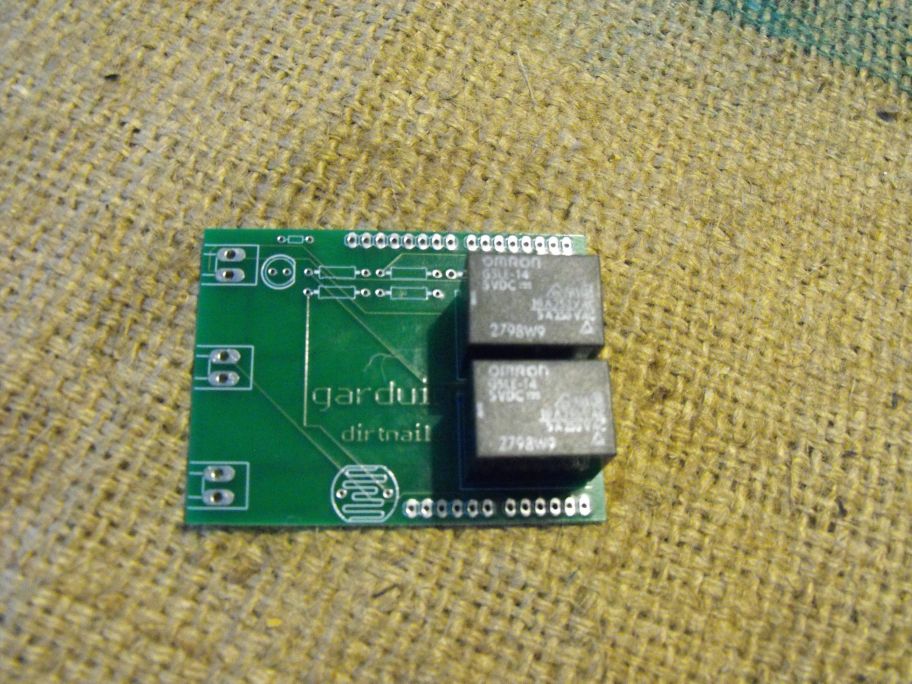
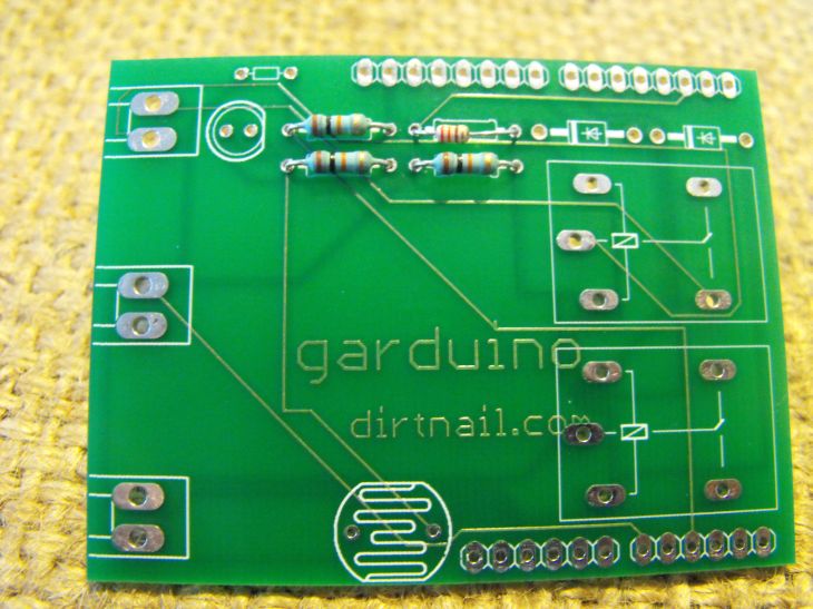
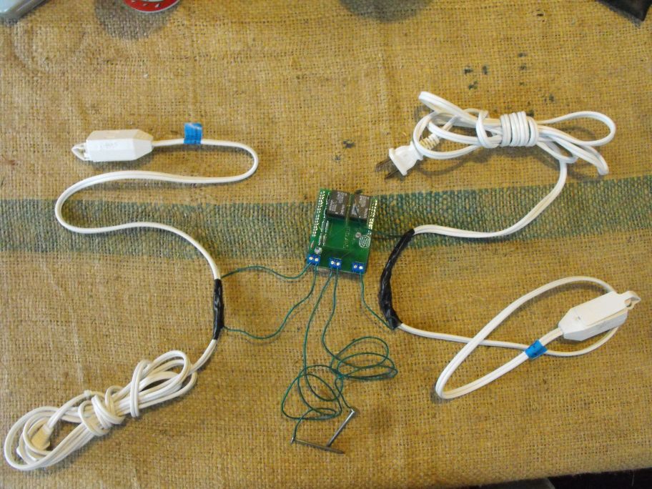
Assembling the PCB
Click on the text for more detail and video of the assembly step!
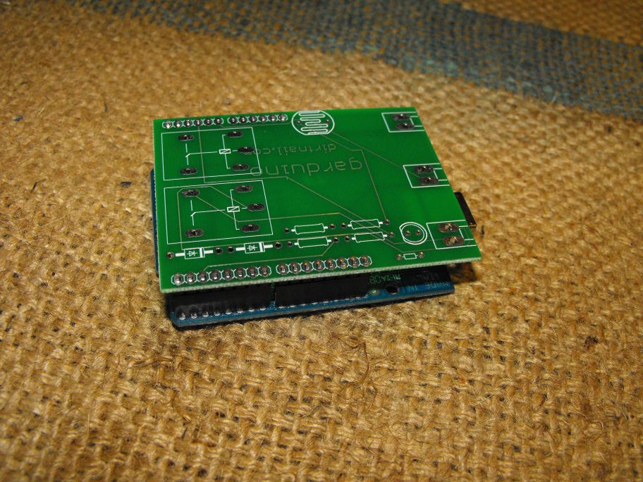
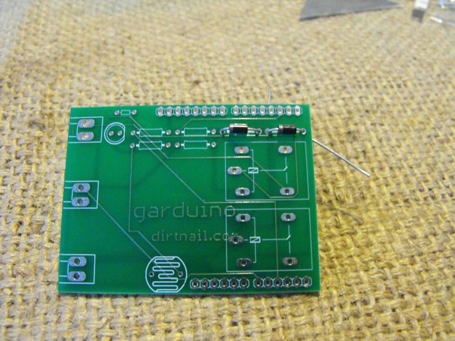
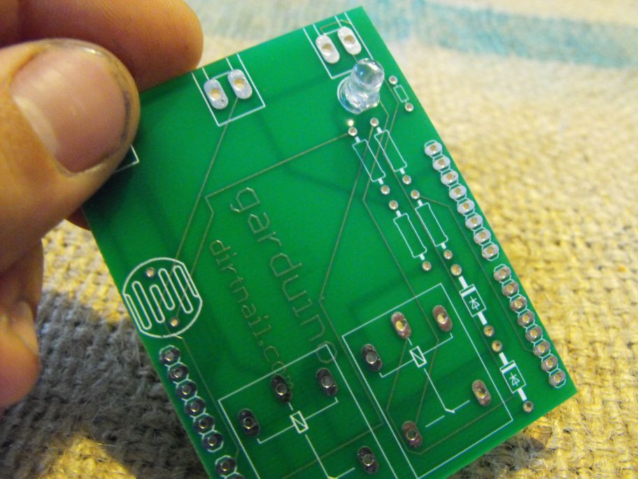
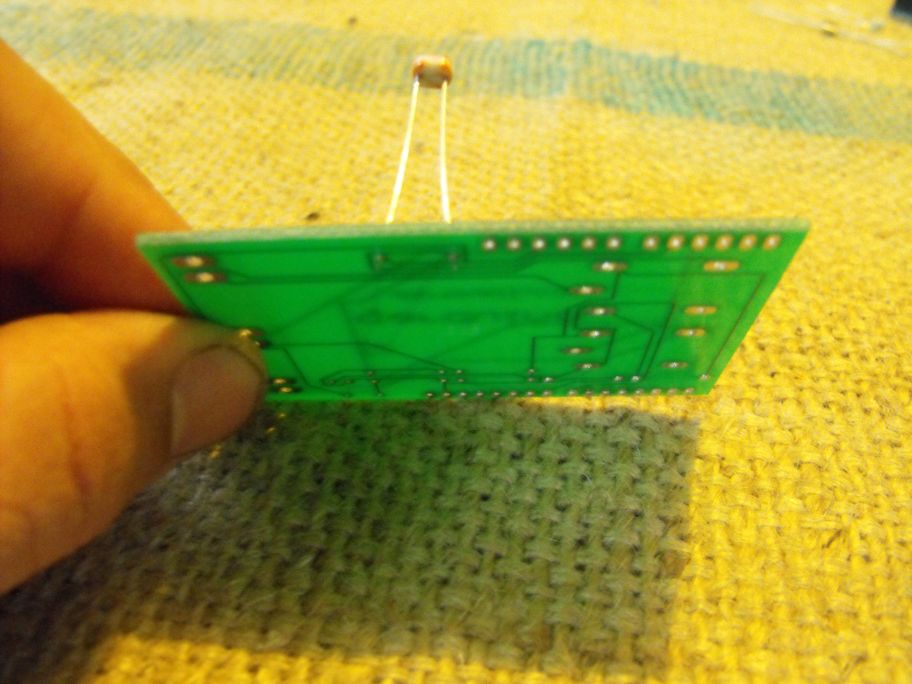
Attach the thermistor to the board, and trim the excess leads.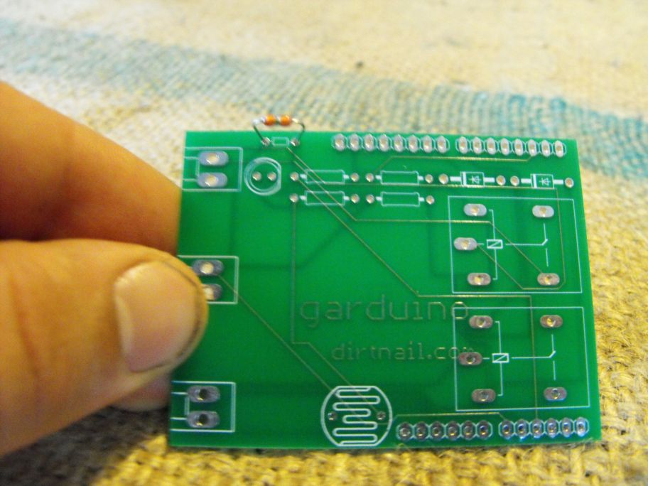
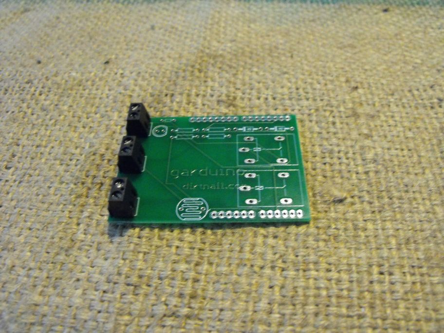
Attach a small piece of electrical tape to the bottom of the Garduino shield below the terminal board connectors. This prevents the USB connector on the Arduino from shorting out the terminal board connector.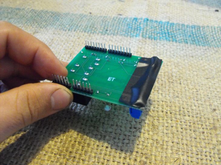
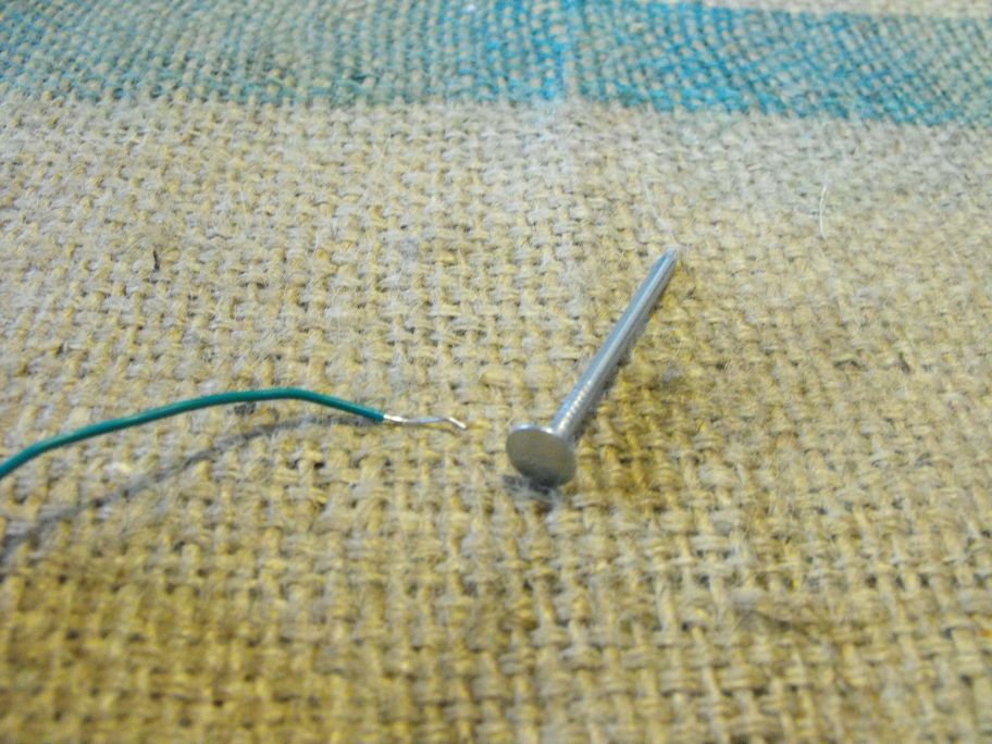
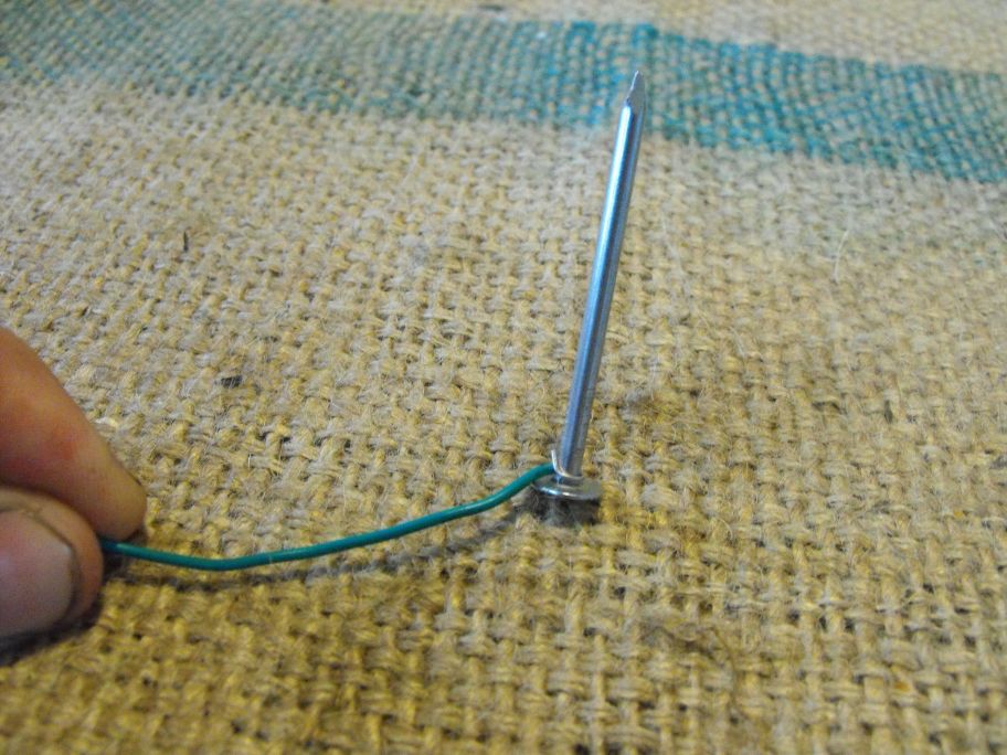
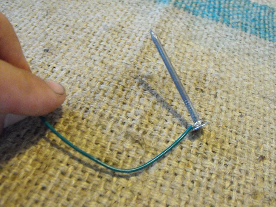
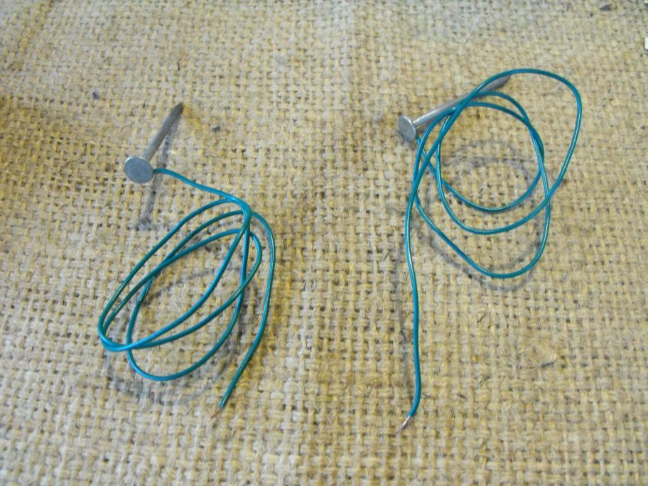
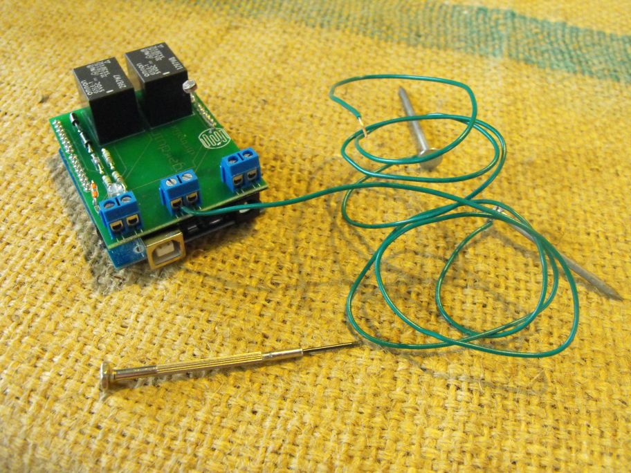
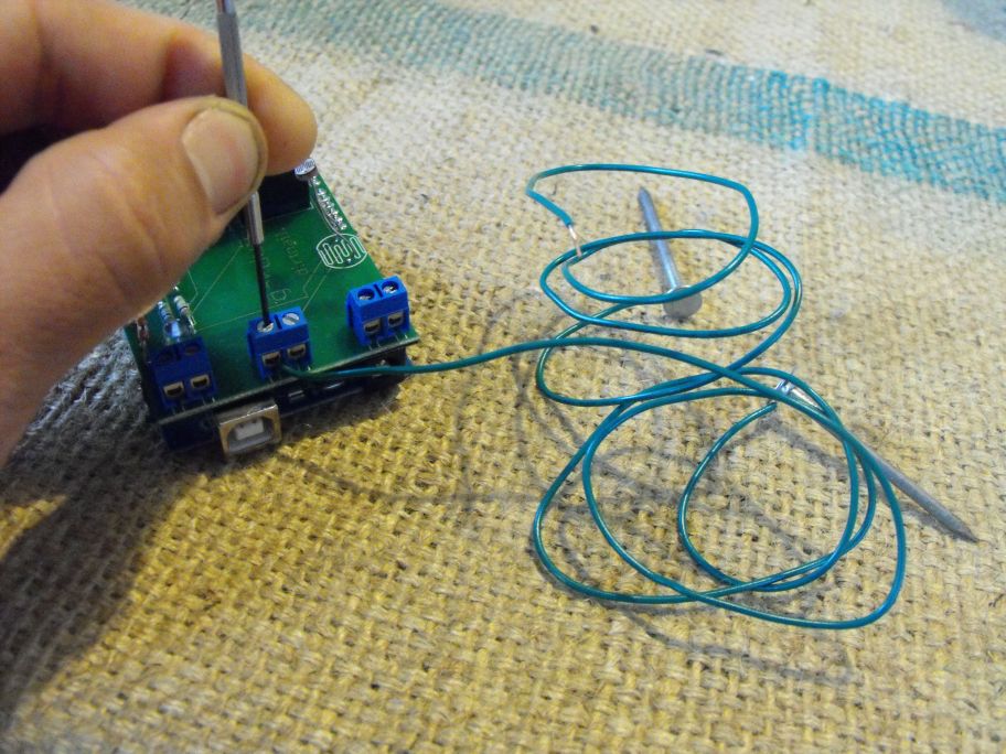
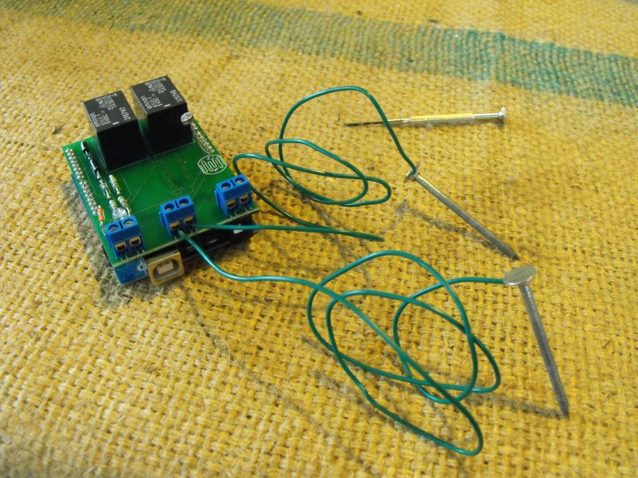
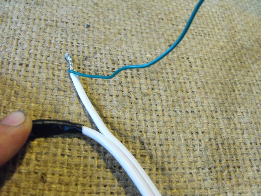
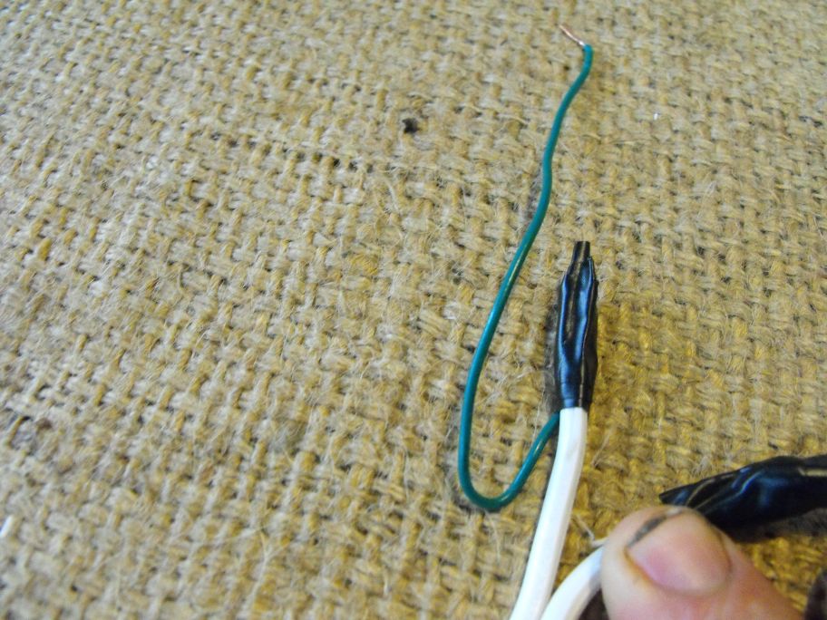
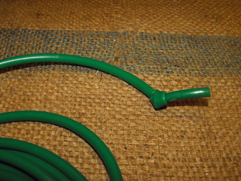
Creating the Moisture Sensor
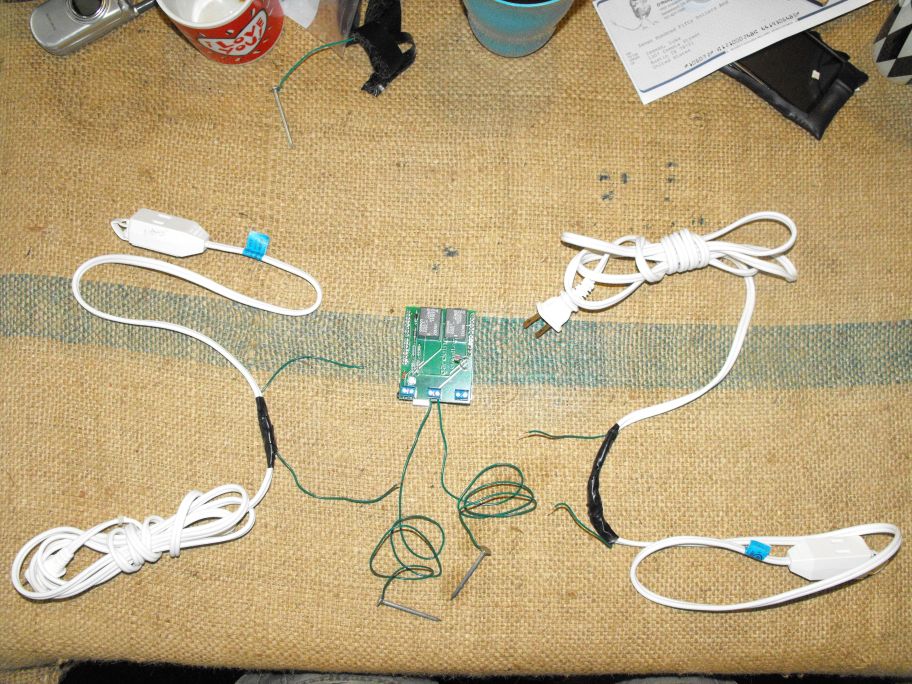
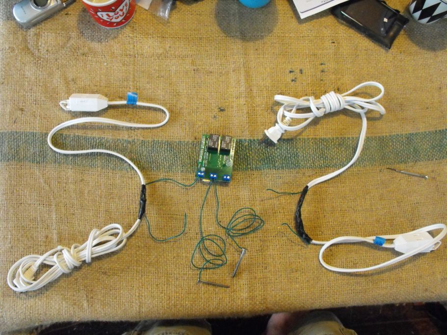
Modifying the Extension Cords
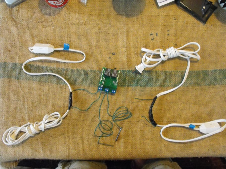
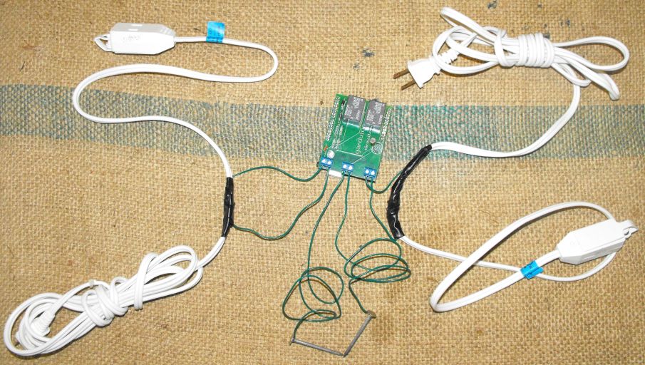
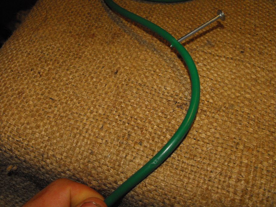
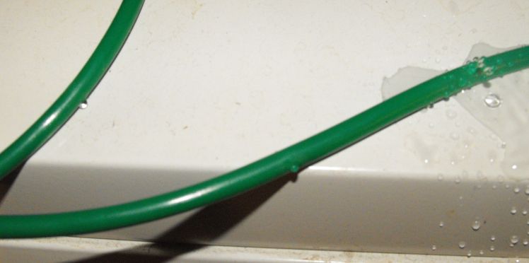
Creating the Sprinkler Hose
Programming Your Garduino
If you're brand-new to Arduino, check out at least the first few lessons of Ladyada's awesome Arduino tutorials here first.
Here's the latest revision of the code for the Garduino:
//include the datetime library, so our garduino can keep track of how long the lights are on
#include <DateTime.h>
//define analog inputs to which we have connected our sensors
int moistureSensor = 0;
int lightSensor = 1;
int tempSensor = 2;
//define digital outputs to which we have connecte our relays (water and light) and LED (temperature)
int waterPump = 7;
int lightSwitch = 8;
int tempLed = 2;
//define variables to store moisture, light, and temperature values
int moisture_val;
int light_val;
int temp_val;
//decide how many hours of light your plants should get daily
float hours_light_daily_desired = 14;
//calculate desired hours of light total and supplemental daily based on above values
float proportion_to_light = hours_light_daily_desired / 24;
float seconds_light = 0;
float proportion_lit;
//setup a variable to store seconds since arduino switched on
float start_time;
float seconds_elapsed;
float seconds_elapsed_total;
float seconds_for_this_cycle;
void setup() {
//open serial port
Serial.begin(9600);
//set the water, light, and temperature pins as outputs that are turned off
pinMode (waterPump, OUTPUT);
pinMode (lightSwitch, OUTPUT);
pinMode (tempLed, OUTPUT);
digitalWrite (waterPump, LOW);
digitalWrite (lightSwitch, LOW);
digitalWrite (tempLed, LOW);
//establish start time
start_time = DateTime.now();
seconds_elapsed_total = 0;
}
void loop() {
// read the value from the moisture-sensing probes, print it to screen, and wait a second
moisture_val = analogRead(moistureSensor);
Serial.print("moisture sensor reads ");
Serial.println( moisture_val );
delay(1000);
// read the value from the photosensor, print it to screen, and wait a second
light_val = analogRead(lightSensor);
Serial.print("light sensor reads ");
Serial.println( light_val );
delay(1000);
// read the value from the temperature sensor, print it to screen, and wait a second
temp_val = analogRead(tempSensor);
Serial.print("temp sensor reads ");
Serial.println( temp_val );
delay(1000);
Serial.print("seconds total = ");
Serial.println( seconds_elapsed_total );
delay(1000);
Serial.print("seconds lit = ");
Serial.println( seconds_light);
delay(1000);
Serial.print("proportion desired = ");
Serial.println( proportion_to_light);
delay(1000);
Serial.print("proportion achieved = ");
Serial.println( proportion_lit);
delay(1000);
//Serial.print("proportion achieved = ");
//long(proportion_lit);
//Serial.println( proportion_lit );
//delay(1000);
//turn water on for 10 seconds if moisture_val is less than 800, turn it off, then wait a second
if (moisture_val < 850)
{
digitalWrite(waterPump, HIGH);
delay (10000);
digitalWrite(waterPump, LOW);
delay (1000);
}
//update time, and increment seconds_light if the lights are on
seconds_for_this_cycle = DateTime.now() - seconds_elapsed_total;
seconds_elapsed_total = DateTime.now() - start_time;
if (light_val > 600)
{
seconds_light = seconds_light + seconds_for_this_cycle;
}
//cloudy days that get sunny again: turn lights back off if light_val exceeds 900. this works b/c the supplemental lights aren't as bright as the sun:)
if (light_val > 900)
{
digitalWrite (lightSwitch, LOW);
}
//turn off lights if proportion_lit>proportion_to_light, and then wait 5 minutes
if (proportion_lit > proportion_to_light)
{
digitalWrite (lightSwitch, LOW);
delay (300000);
}
//figure out what proportion of time lights have been on
proportion_lit = seconds_light/seconds_elapsed_total;
//turn lights on if light_val is less than 600 and plants have light for less than desired proportion of time, then wait 10 seconds
if (light_val < 600 and proportion_lit < proportion_to_light)
{
digitalWrite(lightSwitch, HIGH);
delay(10000);
}
//turn on temp alarm light if temp_val is less than 850 (approximately 50 degrees Fahrenheit)
if (temp_val < 850)
{
digitalWrite(tempLed, HIGH);
}
}
Note the inclusion of the datetime library, which you can install from here. Unzip to the 'libraries' folder of your arduino directory and you'll be good to go.
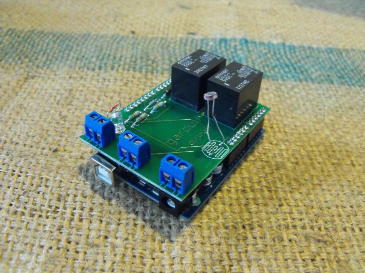
Grow Away!
Attach your pump and light systems, and grow away! Check your seed packets (you saved them, right?) to see how many weeks until your plants should be ready for harvest (The included swiss chard seeds should take ~50 days from planting to harvesting). But don’t be surprised if they’re ready sooner than that! If they seem to be growing too slowly, check your watering and lighting routines.
Expanding From Here
I don’t expect this beta Garduino to get everyone
gardening and save the world; that’s an exercise for
readers to solve with their improvements. But here
are some initial ideas:
If many people start recording the efficiency and convenience of this automated approach to gardening, then maybe we can even grow more food of better quality with less energy. Happy Garduino-ing!